How to Select The Neutral Grounding Resistor For an 11kV Power System?
Writer: admin Time:2025-12-15 14:20:40 Browse:370℃
1. Introduction: The Role of Neutral Grounding in Power Systems
The integrity and reliability of a power distribution network fundamentally depend on its earthing (grounding) strategy. For medium-voltage (MV) systems, particularly those operating at 11 kV, the choice of neutral grounding method is critical for limiting overvoltages, ensuring safety, and enabling sensitive relay protection. While high-voltage systems (e.g., 110 kV and above) often utilize solid grounding, 11 kV distribution networks, especially those with extensive cable sections, frequently adopt Resistance Grounding via a Neutral Grounding Resistor (NGR).
This paper details the rationale for using resistance grounding in 11 kV systems, outlines the crucial steps for calculating the optimal NGR resistance value, and provides guidelines for selecting the associated hardware, including the NGR cubicle and auxiliary components.
2. Why Resistance Grounding is Necessary for 11 kV Networks
In an 11 kV system, single-line-to-ground (SLG) faults are the most common fault type. The two primary reasons for installing an NGR are controlling the resulting transient overvoltages and providing sufficient fault current for protective relays.
2.1. Controlling Transient Overvoltages
When an 11 kV system is ungrounded (isolated neutral), an SLG fault causes the voltage on the healthy phases to rise to the line-to-line voltage (UL), or 11 kV. More critically, the fault can excite transient resonant overvoltages (also known as restriking or arcing ground phenomena). These transients can reach 5 to 8 times the system’s phase voltage (Uph), severely stressing the insulation of equipment (cables, switchgear, and transformers), leading to premature failure.
By inserting a resistor (NGR) between the transformer neutral point and the earth, the system is classified as a Low-Resistance Grounded System. The NGR provides a resistive path to dissipate the energy stored in the system’s capacitance, effectively damping these harmful transient overvoltages and restricting the healthy phase voltage rise, typically below 1.4 to 1.5 times Uph.
2.2. Ensuring Sensitive Relay Protection
In an ungrounded system, the fault current during an SLG fault is limited solely by the system’s charging capacitance (IC), which is often too low to reliably operate conventional overcurrent relays.
The NGR forces a controlled level of fault current (IN) to flow during an SLG fault. This current must be high enough to:
Ensure selectivity: Only the faulted feeder is tripped.
Ensure sensitivity: The magnitude of the current must reliably exceed the pickup settings of the earth-fault relays (Zero Sequence Current Protection).
3. Calculating the Optimal NGR Resistance Value (RN)
The selection of the NGR value (RN) is a trade-off, balancing the need to limit overvoltages (which requires a high RN) against the need to ensure relay sensitivity (which requires a low RN).
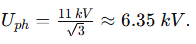
For an 11 kV system,
3.1. Objective 1: Overvoltage Limitation (The Upper Bound for RN)
To keep the transient overvoltages within acceptable limits, the NGR resistance must be less than a value defined by the total system charging current. A widely adopted standard requires the transient overvoltage to be limited to a factor (kU), typically 1.4 to 1.5, of the rated phase voltage.
The NGR resistance must satisfy the following inequality to ensure effective damping:
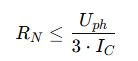
RN: Neutral Grounding Resistance (Ω).
Uph: System Phase Voltage (6.35 kV).
IC: The total system charging current (or total zero-sequence capacitive current) that flows from all feeders during an SLG fault (A). This value must be accurately determined through network analysis.
In practice, the actual resistance chosen is often slightly higher than the calculated value to minimize circulating currents while still providing adequate damping.
3.2. Objective 2: Relay Sensitivity (The Lower Bound for RN)
The NGR must ensure that the resulting fault current (IN) is sufficient to trip the protective relays in a timely and selective manner. The minimum fault current (INmin) required is determined by the most insensitive relay in the system, typically the backup earth-fault relay on the feeder or transformer.
The minimum zero-sequence fault current must be greater than the maximum relay setting:
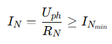
Rearranging for the resistance:
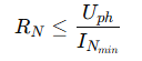
INmin: The pre-determined minimum required fault current (A), which is set by the protective relay requirements, including safety margins (Krel). Typically, INmin is set between 200 A to 1000 A for 11 kV systems, depending on the network size and standards.
3.3. Determining the Final NGR Specification
The final selected RN value is chosen to be the largest resistance that simultaneously satisfies the overvoltage damping requirement (Objective 1) and the minimum current requirement for relay protection (Objective 2).
The RN must also be specified with a current rating (Irated) and a time rating (Trated).
Irated: This is the maximum allowed fault current: Irated = Uph / RN.
Trated: This is the time the resistor must safely withstand the fault current without damage, typically 5, 10, or 30 seconds, corresponding to the longest tripping time of the backup protection.
4. Selecting the Neutral Grounding Resistor Cubicle and Auxiliaries
The NGR cubicle (also called the Neutral Earthing Resistor, NER, cabinet) is a complete solution housing the resistor elements and all necessary monitoring accessories.
4.1. Resistor Element Material and Design
The resistor elements are typically constructed from either:
Stainless Steel Alloys (e.g., 304, 316): Highly common due to their high specific resistance, corrosion resistance, and ability to handle high temperatures.
Cast Iron or Fe-Cr-Alloy: Used in specific high-power, low-resistance applications.
The elements are usually arranged in a bank, often in a modular, suspended design to maximize airflow and minimize contact with the enclosure base, facilitating heat dissipation.
4.2. Cubicle Material and Insulation
Cabinet Material: The enclosure is typically fabricated from painted mild steel or stainless steel (304 or 316) for outdoor installations in corrosive environments.
Ingress Protection (IP Rating): Outdoor cabinets must have an appropriate IP rating, commonly IP54 or higher, to protect against dust and water.
Insulation: The resistor bank and associated busbars must have appropriate insulation suitable for the system voltage (11 kV) with a robust margin, including adequate clearance and creepage distances to prevent flashovers.
4.3. Auxiliary Equipment and Monitoring
The NGR cubicle integrates several critical components for monitoring and protection:
A. Current Transformer (CT)
A dedicated Zero-Sequence Current Transformer (CT) is mounted around the neutral conductor (between the transformer neutral and the resistor terminal).
Purpose: To measure the fault current flowing through the NGR.
Specification: The CT ratio must be selected based on the calculated Irated of the NGR (e.g., if Irated = 500 A, the CT ratio might be 500/5 A). The secondary winding feeds the earth-fault relays.
B. Voltage Transformer (PT or VT) / Monitoring System
A Neutral Voltage Transformer (NVT) is sometimes installed parallel to the resistor or directly connected to the neutral point.
Purpose: To monitor the neutral-to-ground voltage (UN) during an SLG fault. The presence of a voltage confirms a fault condition.
Smart Monitoring: Modern systems increasingly integrate a Remote Monitoring Unit (RMU) or smart controller. This system continuously measures UN and IN, provides status indicators (resistor continuity, fault detection), and communicates data remotely via SCADA/DCS systems.
C. Disconnector and Surrounding Protection
An air-break disconnector or load break switch is often installed on the primary side (at the transformer neutral) to allow isolation of the NGR for maintenance. Surge arresters may also be installed across the NGR terminals to protect the resistor and transformer neutral from transient switching or lightning surges.
5. Illustrative Example for an 11 kV System
Scenario: An 11 kV distribution network in a metropolitan area requires an NGR installation.
System Parameters:
Rated Voltage (UL): 11 kV
Phase Voltage (Uph): 6.35 kV
Total calculated system zero-sequence capacitive current (IC): 50 A (determined by cable lengths and types).
Minimum required zero-sequence fault current for reliable relay operation (INmin): 350 A.
Required Time Rating (Trated): 10 seconds.
Calculation:
Overvoltage Limitation (Objective 1):
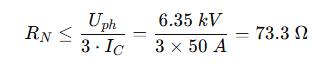
To control overvoltages, R_N must be less than 73.3Ω.
Relay Sensitivity (Objective 2):
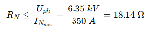
To ensure minimum required fault current, R_N must be less than 18.14Ω.
Final Selection:
Both conditions must be met. Since 18.14Ω is the stricter limit, the practical choice for the nominal resistance value should be slightly less than or equal to this.
Selected Resistance (RN): 18Ω
Calculated Rated Current ( Irated):
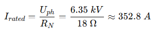
NGR Specification: 18Ω / 353 A / 10 s
Auxiliary Selection: A Current Transformer with a ratio of 400/5 A (or 350/5 A) would be selected to monitor the fault current.
This selection ensures that the transient overvoltages are adequately suppressed while providing 353 A of ground fault current, safely above the 350 A requirement for the protective relays.
6. Conclusion
The careful design and specification of the Neutral Grounding Resistor are paramount to the safe and reliable operation of any 11 kV distribution network. By accurately balancing the conflicting requirements of overvoltage suppression (limited by IC) and relay sensitivity (limited by INmin), engineers can determine the optimal resistance value. Furthermore, selecting a robust cubicle with appropriate auxiliary equipment, such as correctly ratioed CTs and smart monitoring systems, ensures the longevity and effectiveness of the earth fault protection scheme, protecting valuable assets and maximizing service continuity.
Related Articles:
How to Accurately Calculate the Neutral Grounding Resistance Value of a Transformer
Global Top 8 Neutral Grounding Resistor (NGR)Manufacturers
Transformer Neutral Grounding Methods and Applications for High-, Medium-, and Low-Voltage Systems
Solid, Resistance, and Ungrounded Systems — Which Is Safer for your Network?
Why Does the Neutral Point of a Large Generator Need to be Reliably Grounded?
CATEGORIES
- Neutral Grounding Resistor for Transformer
- Generator Neutral Grounding Resistor
- Low Voltage Neutral Grounding Resistor
- Neutral Grounding Arc Suppression Coils (Peterson Coil)
- Neutral Point Gap Grounding Protection Device
- Nitrogen Injection Fire Protection System for Transformer (NIFPS)
- Transformer Air-Cooled Control Equipment
- Nonlinear Neutral Grounding Equipment
LATEST NEWS
- Why Does the Neutral Point of a Large Generator Need to be Reliably Grounded?
- Transformer Neutral Grounding Methods and Applications for High-, Medium-, and Low-Voltage Systems
- How to Accurately Calculate the Neutral Grounding Resistance Value of a Transformer
- Global Top 8 Neutral Grounding Resistor (NGR)Manufacturers
- Neutral Grounding Resistor (NGR) Sizing – Step-by-Step Practical Guide
CONTACT US
WhatsApp: +86-18631228466
Tel: +86-312-5959618
Email: info@orionresistors.com
Add: No. 79, Fuchang Road, Zhongguancun Entrepreneurship Base, Baoding City,China