

Transformer Neutral Grounding Resistor
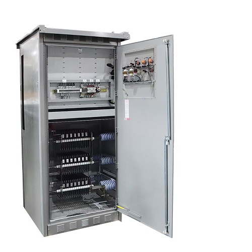
- Product Feature:The OR-TN series Neutral Grounding Resistor (NGR) Cabinet is a specialized device that safely grounds transformer neutrals in 6-66kV systems. It limits fault current to protect equipment from dangerous overvoltages, suppresses electrical arcs, and ensures system stability. Its robust design features high-temperature resistant resistors, an intelligent controller for continuous monitoring, and a corrosion-resistant cabinet for reliable operation in demanding environments.
- INQUIRY
Overview
Under normal conditions, the three-phase neutral point of a generator or transformer remains balanced, with its potential close to zero. The neutral point acts as the system's reference, maintaining voltage symmetry and providing a controlled grounding path. If the neutral insulation is damaged, the grounding resistor becomes open-circuited, or unintended grounding occurs, the system loses itsvoltage reference. This leads to phase voltage imbalance (one phase may rise to line voltage level) causing insulation over-stress, partial discharge, or equipment damage. Conversely, if the neutral point is short-circuited or the grounding resistor fails, the single-phase fault current can surge, resulting in false protection trips, overheating, or even winding burnout. Severe conditions may cause arc grounding, secondary over-voltage, and cascading trips, threatening overall system stability.
To prevent such hazards, transformer neutral grounding ensures safe and reliable system operation by stabilizing voltage, limiting overvoltage, and enabling fault protections in low-, medium-, and high-voltage networks. When a single-phase-to-ground fault occurs, grounding forms a loop through the phase conductor, ground, and neutral point, generating sufficient current to activate protective relays and isolate the fault. Neutral grounding also provides a discharge path for lightning and switching surges, thereby protecting insulation and extending equipment lifespan.The Neutral Grounding Resistor (NGR) cabinet fulfills these functions by inserting a resistor between the neutral and ground. It limits fault current to a safe level while ensuring accurate relay operation, achieving an effective balance between protection sensitivity and system safety.

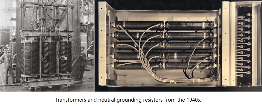
In the late 19th century, many power systems were ungrounded, leading to destructive transient overvoltages and "arc grounding" faults. By the 1910s and 1920s, engineers realized that grounding the neutral point through a resistor could limit fault currents and stabilize system voltage. Early NGRs were large and made from cast iron grids or stamped steel plates, stacked on large outdoor supports. These "resistor banks" relied on natural convection for cooling. As power density increased, materials evolved from simple cast iron to stainless steel and special alloys, which offered better temperature coefficients and corrosion resistance. Designs also shifted from open-frame structures to fully enclosed, IP-rated ventilated cabinets to prevent environmental degradation. Today, modern NGRs are precision-engineered components, often integrated with smart monitoring systems to detect fault duration and temperature rise in real-time.
The OR-TN Series Transformer Neutral Grounding Resistor Cabinet, developed by ORION RESISTOR, is a complete set of specialized equipment designed specifically for transformer neutral grounding applications. It includes both High Resistance Grounding (HRG) and Low Resistance Grounding (LRG) systems, suitable for installation in 6–66 kV power generation auxiliary systems, substation distribution networks, and industrial or mining cable systems, providing a stable and secure neutral grounding solution for power systems.
The High Resistance Grounding (HRG) system is typically used in low-voltage systems (≤1 kV) or medium-voltage distribution networks (3.3–6.6 kV), such as mines, data centers, and factories. Its main feature is that the ground fault current is limited to 5–10 A, helping to prevent system shutdowns and facilitate single-phase fault location.
The Low Resistance Grounding (LRG) system is mainly applied to high-voltage generator and transformer systems (6.6–35 kV), such as powerstations, petrochemical facilities, and heavy industrial networks. The ground fault current typically ranges from 100 A to 1000 A, ensuring sufficient current for protective devices to operate effectively and quickly isolate faults.
10 Key Parameters for Selecting Neutral Grounding Resistors (NGR).
How to Accurately Calculate the Neutral Grounding Resistance Value of a Transformer?
Solid, Resistance, and Ungrounded Systems — Which Is Safer for your Network?
Global Top 8 Neutral Grounding Resistor (NGR)Manufacturers
Star-Connected Transformer Neutral Grounding Diagram:

Delta-Connected Transformer Neutral Grounding Diagram:
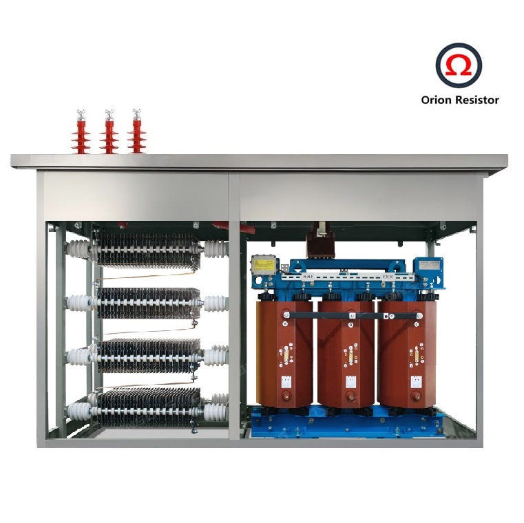
Since a delta-connected winding does not provide a neutral point, a grounding transformer (typically with a Δ-Y connection) is employed. The transformer secondary is derived and converted into a star configuration to obtain a neutral point, which is then connected to the neutral grounding resistor through the grounding resistor cabinet, as illustrated in the diagram.

Functional Features of OR-TN Resistor:
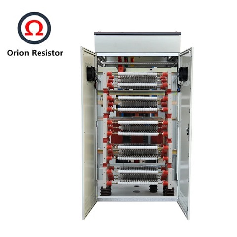
1. Resistor element: Made of high-quality non-metallic special materials or nickel-chromium alloy with stainless steel, ensuring stable resistance, high conductivity, strong current-carrying capacity, high-temperature endurance, and flameproof and explosion-proof performance.
2. Cabinet structure: Designed primarily for indoor use, fabricated from powder-coated cold-rolled steel plates or stainless steel, providing corrosion resistance and a high degree of protection.
3. Intelligent controller: Capable of monitoring and recording system zero-sequence current under normal conditions, single-phase ground fault current, grounding duration, system zero-sequence voltage, resistor temperature, as well as ambient temperature and humidity inside the cabinet. It also records the number of grounding operations.
4. Alarm and protection functions: Provides system grounding alarm, ambient over-temperature trip and alarm, resistor over-temperature trip and alarm, resistor open-circuit monitoring alarm, and grounding overtime protection and alarm.
5. Communication interface: Equipped with a communication port to transmit recorded data to the main control room for upper-level computer communication.
Technical Parameters:
Recommended Technical Parameter Table (OR-TN Series)
Voltage Class
Model
System Rated
Voltage(V)
Rated Voltage
L-N (V)
Current
Ratings (A)
Rated Time (s)
Resistance at 25℃(Ω, ±5%)
LV
OR-TN0.38–100–10
380
220
100
10
2.2
OR-TN0.40–100–10
400
230
100
10
2.3
OR-TN0.415–100–10
415
240
100
10
2.4
OR-TN0.48–100–10
480
280
100
10
2.8
OR-TN0.6–100–10
600
350
100
10
3.5
OR-TN0.69–100–10
690
400
100
10
4.0
OR-TN1.2–100–10
1200
690
100
10
6.9
OR-TN2.4–100–10
2400
1400
100
10
13.9
MV
OR-TN3.3–200–10
3300
1900
200
10
9.5
OR-TN3.6–200–10
3600
2080
200
10
10.4
OR-TN4.16–200–10
4160
2400
200
10
12.0
OR-TN6.3–200–10
6300
3640
200
10
18.2
OR-TN6.6–200–10
6600
3800
200
10
19.1
OR-TN7.2–400–10
7200
4150
400
10
10.4
OR-TN10–400–10
10000
5770
400
10
14.4
OR-TN11–400–10
11000
6350
400
10
15.9
OR-TN13.8–400–10
13800
7970
400
10
19.9
OR-TN14.4–400–10
14400
8300
400
10
20.8
OR-TN14.76–600–10
14760
8530
600
10
14.2
OR-TN15–600–10
15000
8660
600
10
14.4
OR-TN20–600–10
20000
11550
600
10
19.2
OR-TN22–600–10
22000
12700
600
10
21.2
OR-TN27.6–600–10
27600
15950
600
10
26.6
OR-TN34.5–600–10
34500
20000
600
10
33.2
HV
OR-TN44–600–10
44000
25400
600
10
42.3
OR-TN66–1000–10
66000
38100
1000
10
38.1
OR-TN69–1000–10
69000
39800
1000
10
39.8
Please note that the technical specifications above are typical values. We specialize in bespoke designs and can customize our grounding resistor cabinets to match your specific electrical parameters and spatial constraints, including voltage, current, resistance, and mechanical dimensions.


Orion Resistors adopt Fe-Cr-Al stainless steel or Ni-Cr grid resistor elements, featuring excellent stability, high temperature resistance, dense oxide film, and long service life.

All Orion Resistors use high-quality circuit breakers, relays, and surge protectors, combined with intelligent control to ensure coordinated operation and accurate fault current limitation.

Why Choose Orion Resistor?
1.High-capacity workshops and standardized assembly lines ensure every grounding resistor meets international performance standards.

2.Every resistor and transformer is built with strict quality control and premium materials for long-term reliability.

3.Comprehensive design verification and high-voltage testing guarantee safety and performance before delivery.

4.Each NGR cabinet is vacuum-sealed to prevent moisture ingress during transport, ensuring stable insulation resistance and reliable electrical performance upon delivery.


Neutral Grounding Resistor FAQ:
1. How to determine the correct grounding resistance value?
Core Standard: IEEE Std 32 / IEC 60071-1
The grounding resistance value must balance fault limitation and protection sensitivity. Incorrect selection may cause either excessive fault current or delayed protection operation.
Formula:
: Line voltage or system voltage
: Protection current setting (typically 200–1000 A)
Example:
For a 10 kV system with a 500 A target fault current,
In practice, 12 Ω is commonly used to align with standard resistor element series.
Verification: Neutral-point voltage displacement ≤ 10 % of phase voltage; steady-state temperature rise within rated limits.
2. How to select the thermal withstand time (time rating)?
Core Standard: IEEE Std C37.101 / IEC 60909
Thermal capacity must match the system’s protection coordination:
Typical distribution networks: Protection clears within 0.2 s → 10 s rating recommended (per IEC type test, 1000 A × 10 s = 5 MJ).
Critical loads (data centers, hospitals): With delayed backup protection (2–3 s), select ≥ 5 s models.
Tip: Certified NGRs clearly mark “1000 A / 10 s” or equivalent; uncertified products may omit this parameter.
3. Which resistor element material ensures long-term stability?
Core Standard: ASTM B344 / IEC 60115
Material determines both lifespan and temperature coefficient:
Nickel-Chromium Alloy (NiCr): Temp. coefficient ≤ 50 ppm/°C; withstands 760 K rise for 10–60 s; lifespan > 20 years.
Stainless Steel (304/316L): High corrosion resistance, especially for marine or chemical sites.
Carbon Steel: Low cost but poor oxidation resistance; resistance drift or fuse risk after 1–2 years.
Recommendation:Indoor/industrial: NiCr alloy balance of cost and performance.
Marine/chemical: 316L stainless steel for corrosion protection.
4. What protection and monitoring functions are essential?
Core Standard: IEC 60255 / IEC 61850
Modern NGR systems must integrate both protective interlocks and remote supervision:
Basic Protections:
Overcurrent trip (aligned with Iset)
Overtemperature alarm (≥ 300 °C)
Door/isolator interlock
Smart Monitoring:
Current + temperature sensors
RS485 / Modbus-RTU communication
SCADA integration (fault current waveform & temperature trend)
Advanced Options:
Fault counter, remote ON/OFF, event log for predictive maintenance.
5. What insulation level and clearance are required for safety?
Core Standard: IEC 60071-1 / IEC 62271-200 / IEEE Std 32
Insulation and creepage design ensure reliability under environmental stress:
For 10 kV systems:
Creepage ≥ 250 mm
Phase-to-earth insulation ≥ 1000 MΩ (2.5 kV megger)
Phase spacing ≥ 125 mm
Enclosure protection:
Standard type: IP55 (industrial)
Enhanced type: IP65 (mining, offshore)
Material:
304/316L stainless steel (≥ 15 yrs anti-corrosion)
Hot-dip galvanized steel (zinc ≥ 85 µm, 10 yrs + durability)
Explosion-proof option: IEC 60079-1 compliant design.
6. How to select the right NGR for high-resistance vs. low-resistance grounding systems?
Core Standard: IEEE Std 142 (Green Book) / IEC 60071
High-Resistance Systems:
1 kΩ – 2 kΩ range, fault current ≤ 10 A; ideal for data centers & hospitals.
Use ±1 % precision metal film resistors.Low-Resistance Systems:
5 Ω – 50 Ω range, fault current 50 – 1000 A; used in industrial grids.
Use wire-wound resistors ≥ 5 kW.Hybrid Systems:
With arc-suppression coil + resistor combination; short-time impulse type required, ensuring “arc extinction before resistor insertion.”
7. How does installation environment affect NGR design?
Core Standard: IEC 60529 / IEC 60068
Environment determines enclosure and cooling method:
Outdoor / humid: IP54–IP65, sealed cabinet with anti-condensation heater.
Indoor / control room: IP30 adequate, ≥ 5 kW units require forced air cooling + fan fault alarm.
High altitude: Increase insulation rating by 10 % per 1000 m.
8. What about system protection coordination and relay settings?
Core Standard: IEC 60255-151 / IEEE C37.101
Changing to an NGR (low-resistance grounding) requires relay coordination:
Enable zero-sequence protection.
Adjust pickup ≤ 300 A to coordinate with upstream grid.
Failure to adjust may cause unwanted feeder tripping during faults.
9. Any special considerations for systems with distributed generation (e.g. solar, wind)?
Core Standard: IEC 61727 / IEEE 1547
Distributed sources may alter fault current direction.
Check inverter fault contribution and ensure directional earth-fault relays are used to avoid mal-operation.
10. How to design NGRs for Δ-connected transformers without a neutral point?
Core Standard: IEEE Std 32 / IEC 60076-3
Use a Z-type grounding transformer + NGR combination:
Grounding transformer capacity ≈ (system capacitive current × 10 kV) → e.g. 25 A → 250 kVA.
Zero-sequence impedance ≤ 5 Ω.
No-load loss ≤ 0.5 %; negligible under normal operation.
Verify thermal coordination between the grounding transformer and resistor assembly.
11. How should the residual current device (RCD/ELCB) be selected for client protection?
Core Standard: IEC 61008 / IEC 61009
Use current-operated type (voltage-type RCDs only for ungrounded systems).
Typical settings:
Single-device: 30 mA / 0.1 s
Large circuits: 50–100 mA
Use 3-pole + N type for 3-phase loads to avoid false tripping due to N/E confusion
RELATED PRODUCTS

CATEGORIES
- Neutral Grounding Resistor for Transformer
- Generator Neutral Grounding Resistor
- Low Voltage Neutral Grounding Resistor
- Neutral Grounding Arc Suppression Coils (Peterson Coil)
- Neutral Point Gap Grounding Protection Device
- Nitrogen Injection Fire Protection System for Transformer (NIFPS)
- Transformer Air-Cooled Control Equipment
- Nonlinear Neutral Grounding Equipment
LATEST NEWS
- Why Does the Neutral Point of a Large Generator Need to be Reliably Grounded?
- Transformer Neutral Grounding Methods and Applications for High-, Medium-, and Low-Voltage Systems
- How to Accurately Calculate the Neutral Grounding Resistance Value of a Transformer
- Global Top 8 Neutral Grounding Resistor (NGR)Manufacturers
- Neutral Grounding Resistor (NGR) Sizing – Step-by-Step Practical Guide
CONTACT US
WhatsApp: +86-18631228466
Tel: +86-312-5959618
Email: info@orionresistors.com
Add: No. 79, Fuchang Road, Zhongguancun Entrepreneurship Base, Baoding City,China