Generator Neutral Grounding Resistor
- Product Feature:OR-GN Generator Neutral Grounding Resistor Cabinet, compact & lightweight, fits generators. High-res grounding limits overvoltage, protects stator/windings. Premium resistors (heat-resistant to 1600℃), with transformers, CTs for monitoring. Ensures generator safety.
- INQUIRY
Overview
The generator is the primary driving source of a power system and must be equipped with adequate fault-response capability during operation. The grounding method of the generator neutral point plays a critical role in this process.In modern practice, the generator neutral point is typically grounded through high resistance. High-resistance grounding effectively suppresses ground-fault current, preventing stator winding damage and reducing transient overvoltages caused by arc-grounding faults. Among various high-resistance grounding schemes, the most reliable is the combination of a single-phase transformer with a resistor.
When a single-phase-to-ground fault occurs in the generator circuit and the current exceeds the allowable limit, arc-grounding overvoltages may be generated. Since the generator insulation withstand level is relatively low, this condition can lead to insulation breakdown. Excessive ground current may also cause burning or sintering of the generator core.
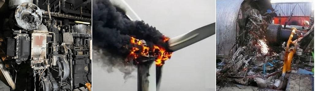
By applying high-resistance grounding at the generator neutral point, arc-grounding overvoltage can be effectively limited, core damage minimized, and the sensitivity of protective relays enhanced. This ensures reliable tripping action, restricts overvoltage within 2.6 times the phase voltage, prevents arc re-ignition, avoids insulation failure due to arc gaps, and suppresses ferroresonance overvoltage, thereby safeguarding the safe and stable operation of the generator.
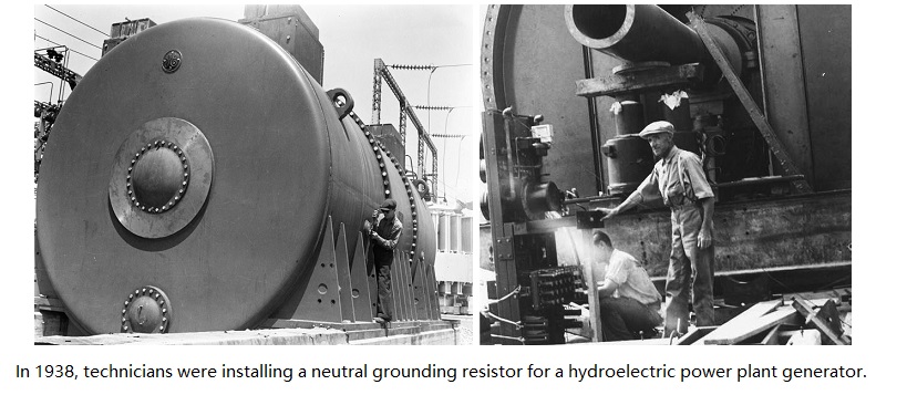
In the late 19th century, many power systems were ungrounded, leading to destructive transient overvoltages and "arc grounding" faults. By the 1910s and 1920s, engineers realized that grounding the neutral point through a resistor could limit fault currents and stabilize system voltage. Early NGRs were large and made from cast iron grids or stamped steel plates, stacked on large outdoor supports. These "resistor banks" relied on natural convection for cooling. As power density increased, materials evolved from simple cast iron to stainless steel and special alloys, which offered better temperature coefficients and corrosion resistance. Designs also shifted from open-frame structures to fully enclosed, IP-rated ventilated cabinets to prevent environmental degradation. Today, modern NGRs are precision-engineered components, often integrated with smart monitoring systems to detect fault duration and temperature rise in real-time.
Features and Advantages:
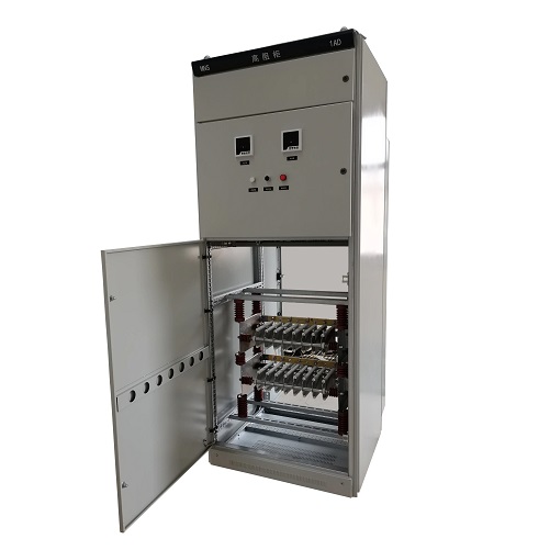
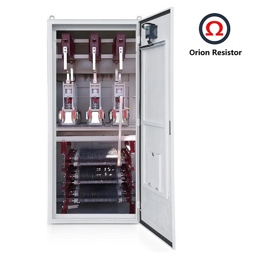
The OR-GN Generator Neutral Grounding Resistor Cabinet manufactured by our company is compact in size and lightweight in design. The built-in transformer has excellent impulse resistance, flame-retardant performance, and low partial discharge level.
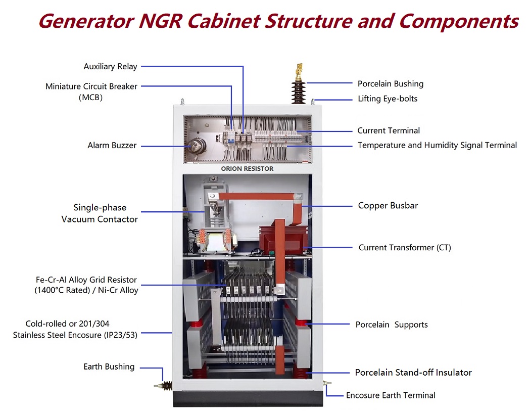
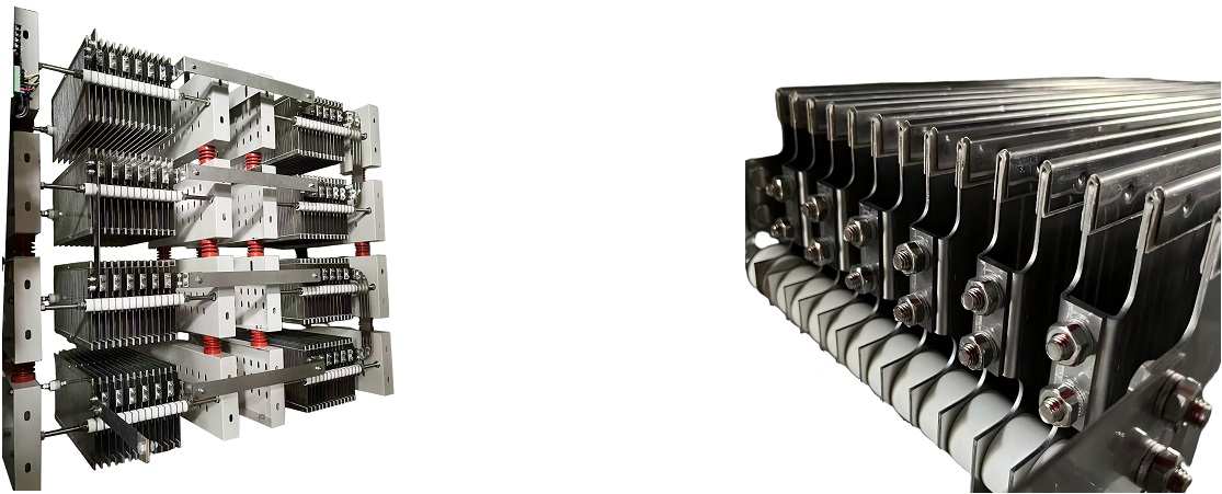
Resistors: Fabricated from premium stainless-steel nickel-chromium alloy (Cr20Ni80) or non-metallic materials such as carbon valve plates and zinc oxide valve plates. These resistors feature high conductivity, strong current-carrying capacity, stable resistance, high thermal coefficient, excellent corrosion resistance, toughness, and the ability to withstand temperatures up to 1600℃ without deformation.
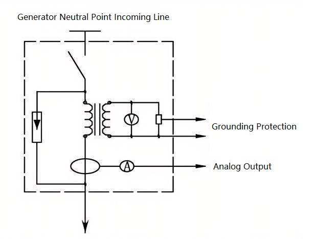
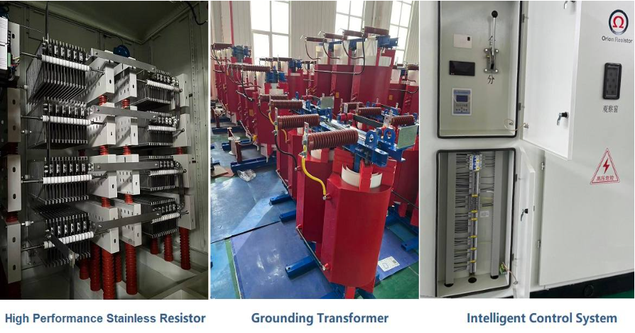
OR-GN Model: Equipped with a dry-type single-phase transformer, resistors, isolating switch, surge arrester, and other electrical components, enabling convenient installation near the generator neutral point.
OR-GN Model: Integrated with current transformers for accurate measurement of neutral current and analog signal output, facilitating monitoring and protection functions.
Technical Parameters:
1. Recommended Technical Parameter Table (OR-GN Series)
Generator Capacity (kW) | 100/125 | 200 | 300 | 600 | 900/1000 | ||||
Generator Rated Voltage (kV) | 10.5 | 13.8 | 15.75 | 18 | 20 | 20 | 24 | 24 | 27 |
Estimated Max. Single-Phase-to-Ground Capacitive Current in the Circuit (A) | 4 | 5 | 6 | 8 | 10 | ||||
Primary Side Voltage of Grounding Transformer (kV) | 10.5/√3 | 13.8/√3 | 15.75/√3 | 18/√3 | 20/√3 | 20/√3 | 24/√3 | 24/√3 | 27/√3 |
Secondary Side Voltage of Grounding Transformer (kV) | 0.22 | 0.22 | 0.22 | 0.22 | 0.22 | ||||
Rated Capacity of Grounding Transformer (kVA) | 30 | 30 | 50 | 50 | 63 | ||||
Secondary Side Resistance Value (Ω) | 1.0 | 0.8 | 0.5 | 0.4 | 0.3 | ||||
Grounding Protection Extraction Voltage (kV) | 0.1 | 0.1 | 0.1 | 0.1 | 0.1 | ||||
10 Key Parameters for Selecting Neutral Grounding Resistors (NGR).
How to Accurately Calculate the Neutral Grounding Resistance Value of a Transformer?
Solid, Resistance, and Ungrounded Systems — Which Is Safer for your Network?
Global Top 8 Neutral Grounding Resistor (NGR)Manufacturers
Dimension Drawing and Wiring Diagram of OR-GN Low Voltage Neutral Grounding Resistor Cabinet:
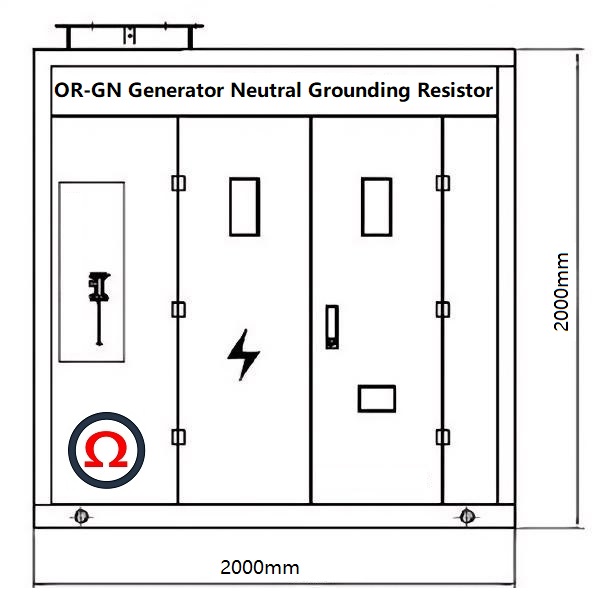
Recommended dimensions for the OR-GN generator neutral grounding resistor cabinet: 1600 x 2000 x 2000 mm (width x length x height).
Note: The cabinet's appearance, dimensions, cabinet material, and color coding can be designed and manufactured to specific customer requirements.

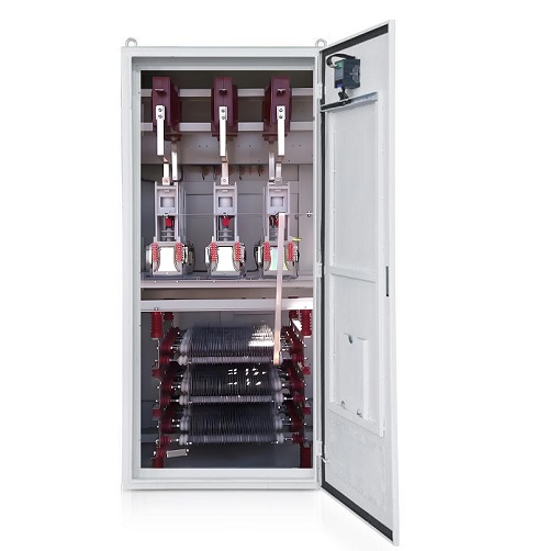
Why should a vacuum contactor be installed in a generator neutral grounding resistor system?
A generator neutral grounding resistor must be equipped with a vacuum contactor because, when multiple generators operate in parallel, only one generator’s neutral point is allowed to be grounded. If more than one neutral is grounded simultaneously, circulating currents and protection malfunctions may occur. The vacuum contactor allows automatic connection and disconnection of the grounding resistor, ensuring system safety and operational flexibility. In contrast, the transformer neutral point usually serves as the system’s single fixed grounding point, which does not require frequent switching. Therefore, a fixed connection or disconnector is sufficient, and a vacuum contactor is not required.


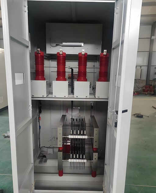
Generator Neutral Grounding Resistor :(Equipped with ABB 10 kV High-Voltage Vacuum Contactor)
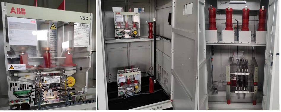

Orion Resistors adopt Fe-Cr-Al stainless steel or Ni-Cr grid resistor elements, featuring excellent stability, high temperature resistance, dense oxide film, and long service life.
All Orion Resistors use high-quality circuit breakers, relays, and surge protectors, combined with intelligent control to ensure coordinated operation and accurate fault current limitation.

Why Choose Orion Resistor:
1.High-capacity workshops and standardized assembly lines ensure every grounding resistor meets international performance standards.

2.Every resistor and transformer is built with strict quality control and premium materials for long-term reliability.
3.Comprehensive design verification and high-voltage testing guarantee safety and performance before delivery.

4.Each NGR cabinet is vacuum-sealed to prevent moisture ingress during transport, ensuring stable insulation resistance and reliable electrical performance upon delivery.


⚡ Generator Neutral Grounding Resistor (GNGR) FAQ:
Common Questions for Power Plants, Data Centers, and Heavy Industry Applications
1️⃣ How to accurately set the grounding resistance value for a generator?
The resistance value should balance fault current limitation and generator excitation protection.
Use the standard formula:
R = UL / (1.732 × Ifault)
where UL is the line voltage, and Ifault is the desired single-phase fault current.
For a 6.6 kV generator, limiting the fault current to 200 A gives R = 6600 / (1.732 × 200) ≈ 19 Ω.
This ensures both effective fault detection and insulation protection.
Typical Applications: Auxiliary generators in power plants, gas turbine backup systems.
2️⃣ How to determine the grounding current duration (thermal withstand time)?
The GNGR’s thermal rating must match the generator’s protection time, usually 10 seconds.
If the protection relay operates within 0.5–1 s, the resistor cabinet should withstand at least 10 s/200 A.
For unmanned systems (e.g., data center backup generators), use models rated 10 s/400 A or higher to handle delayed switching.
Typical Applications: Data center backup power, hospital emergency power systems.
3️⃣ Does the resistor material affect service life?
Yes, greatly. Choose nickel-chromium alloy grid resistors or 316L stainless-steel blade resistors.
These materials remain stable up to 760 °C and can endure short-time high currents.
Mild steel resistors may oxidize or burn open during faults, leading to protection failure.
Typical Applications: Offshore platforms, port diesel generator stations, marine environments.
4️⃣ What protection and monitoring functions should a GNGR include?
A reliable generator grounding resistor system should provide:
Overcurrent protection – prevents prolonged stator fault current;
Temperature detection – alarms at ≥300 °C, trips at ≥400 °C;
Remote communication (RS485 / Modbus) – uploads current and temperature data.
For large or unattended systems, add remote control and fault history recording.
Typical Applications: Power plant auxiliary systems, ship power automation systems.
5️⃣ What environmental conditions affect installation?
Environment directly impacts insulation, protection level, and cooling design:
Outdoor or port installations: IP55–IP65, 304/316L stainless-steel cabinet;
Indoor or containerized units: IP30–IP40, forced-air cooling recommended;
High altitude (>2000 m): increase insulation class by 10–20%.
Typical Applications: Mining power stations, container-type gensets, data center modules.
6️⃣ How to coordinate generator protection settings with the NGR?
When converting to low-resistance grounding, the generator’s zero-sequence protection must be reconfigured.
Recommended settings:
Trip current = 0.2–0.4 × fault current;
Time delay = 0.5–1 s.
Improper coordination can cause nuisance tripping or failure to operate.
Typical Applications: Paralleled generators, CHP (combined heat & power) systems.
7️⃣ What to consider for systems with multiple generators or solar inverters?
Distributed or paralleled systems may reverse fault current direction.
Use a directional earth-fault relay and verify if the GNGR is shared among sources.
Typical Applications: Data center multi-generator setups, microgrid systems.
8️⃣ How to apply an NGR if the generator uses a delta (Δ) winding without neutral?
Use a zig-zag grounding transformer combined with an NGR.
The transformer capacity = system capacitive current × 10 kV, with zero-sequence impedance ≤ 5 Ω.
Typical Applications: Generator synchronization systems, mobile power stations.
9️⃣ How to choose between high-resistance and low-resistance grounding for generators?
High-Resistance Grounding (HRG): limits fault current ≤ 10 A; suitable for data centers, telecom hubs, and other continuous-service systems.
Low-Resistance Grounding (LRG): limits current to 100–1000 A; ideal for power plants, heavy industry, and port generators.
Hybrid systems may use arc-suppression coils + resistors for automatic arc extinction and system protection.
🔟 What are the insulation and safety standards for generator NGRs?
Comply with the following international standards:
IEC 60071 – Insulation coordination
IEEE Std 32 – Design requirements for grounding resistors
IEC 62271-200 – Switchgear design and construction
Recommended protection: IP55 (outdoor) or IP65 (marine).
For 10 kV systems: creepage distance ≥ 250 mm, insulation resistance ≥ 1000 MΩ (tested at 2.5 kV).
Typical Applications: Offshore generator plants, oilfield gas-fired generators.
RELATED PRODUCTS
CATEGORIES
- Neutral Grounding Resistor for Transformer
- Generator Neutral Grounding Resistor
- Low Voltage Neutral Grounding Resistor
- Neutral Grounding Arc Suppression Coils (Peterson Coil)
- Neutral Point Gap Grounding Protection Device
- Nitrogen Injection Fire Protection System for Transformer (NIFPS)
- Transformer Air-Cooled Control Equipment
- Nonlinear Neutral Grounding Equipment
LATEST NEWS
- Why Does the Neutral Point of a Large Generator Need to be Reliably Grounded?
- Transformer Neutral Grounding Methods and Applications for High-, Medium-, and Low-Voltage Systems
- How to Accurately Calculate the Neutral Grounding Resistance Value of a Transformer
- Global Top 8 Neutral Grounding Resistor (NGR)Manufacturers
- Neutral Grounding Resistor (NGR) Sizing – Step-by-Step Practical Guide
CONTACT US
WhatsApp: +86-18631228466
Tel: +86-312-5959618
Email: info@orionresistors.com
Add: No. 79, Fuchang Road, Zhongguancun Entrepreneurship Base, Baoding City,China