What FAT items are required for 3.3kV Neutral Grounding Resistor?
Writer: admin Time:2025-12-18 16:11:14 Browse:224℃
Based on the parameters provided for the 3.3kV / 10A Neutral Grounding Resistor (NGR), the routine factory tests must strictly adhere to the IEEE-32 standard. For equipment with low voltage but high resistance, the testing focuses on resistance precision and thermal stability under high-temperature conditions.
The following is the professional English translation of the detailed factory test procedures:
Routine Factory Test Procedures for 3.3kV NGR
1. Measurement of Resistance
This is the most critical test item used to verify the current-limiting capability of the unit.
Testing Requirement: The nominal resistance is 190.50 Ω with an allowable tolerance of ±10%.
Test Example: Measure using a high-precision bridge or a digital micro-ohmmeter. The actual measured value must fall within the range of 171.45 Ω to 209.55 Ω.
Temperature Correction: The ambient temperature must be recorded during testing (referenced to a baseline of 50℃). The measured value is then converted to the resistance at the reference temperature using the temperature coefficient of 0.00094 / ℃.
2. Dielectric / Applied Voltage Test
This test verifies the insulation strength of the resistor cabinet to ensure no breakdown occurs during high-voltage surges.
Testing Standard: Although the system voltage is 3.3 kV, according to IEEE-32 regulations, the factory dielectric test voltage is typically set at 2.25 x Rated Voltage + 2000V, or performed according to the enclosure's insulation class (usually 10kV or higher).
Acceptance Criteria: Apply the test voltage between the resistor elements and the ground for 60 seconds. There should be no signs of flashover or dielectric breakdown during this period.
3. Insulation Resistance Test
Operation: Before and after the dielectric test, use a 2500V Megger (insulation resistance tester) to measure the insulation resistance of the resistor elements to ground and the control circuits to ground.
Standard: For 3.3kV equipment, the insulation resistance should typically be no less than 100MΩ.
4. Component and Control Circuit Inspection
Resistor Grid Inspection: Inspect the assembly quality of the AISI-304 Stainless Steel Punched Grids. Ensure uniform spacing between plates and no loose connections to prevent short circuits caused by thermal expansion during a 10-second high-current surge.
CT Verification: Perform ratio and polarity tests on the internal Current Transformer (CT) to ensure it accurately captures the 10A ground fault current.
Temperature Rise Limit Verification: Verify that the materials comply with the maximum temperature rise limit of 760℃.
5. Mechanical and Visual Inspection
Ingress Protection (IP) Rating: Inspect door seals and ventilation louvers to ensure compliance with indoor or outdoor installation environment requirements.
Nameplate and Markings: Verify that all parameters (voltage, current, resistance, short-time rating) are consistent with the design drawings.
Warning: Since this device is rated for a working time of only 10 seconds, it is crucial to avoid prolonged power-on during preventive testing in the field!
Below is the Factory Acceptance Test (FAT) procedure for a 3.3kV resistor cabinet.
Technical Specifications and Testing Procedures
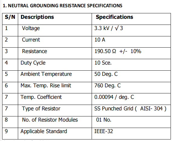
Base Specifications:
Rated Voltage: 3.3 kV/√3
Rated Current: 10 A
Nominal Resistance: 190.50 Ω ± 10%
Step 1: Cold Resistance Test
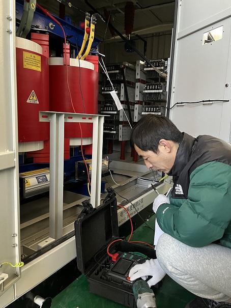
Procedure: Use a high-precision digital micro-ohmmeter to measure the resistance between the incoming terminal and the grounding terminal of the NGR cabinet.
Sample Data: The actual measured value is 192.4 Ω.
Judgment: The specification requires a tolerance of ±10% (resulting in an allowable range of 171.45 Ω to 209.55Ω). Since 192.4 Ω falls within this range, the unit is deemed Qualified.
Step 2: Insulation / Dielectric Test (Power Frequency Withstand Test)
Procedure: Apply a power frequency voltage to the entire resistor assembly relative to the ground. Although the system voltage is 3.3 kV, a higher test voltage is required per the IEEE-32 standard to verify insulation integrity.
Sample Data: Apply 10 kV (or 28 kV if the enclosure is rated for 11 kV systems) for a duration of 1 minute.
Judgment: During the test, there shall be no dielectric breakdown or flashover. If none occur, the unit is Qualified.
Step 3: Temperature Rise and Hot Resistance Verification
Since it is often difficult to provide a high-power source capable of maintaining 10A for 10 seconds (the rated time duration) at the factory, a parameter verification method is typically used:
Procedure: Utilize the temperature coefficient (α = 0.00094 /℃) from the specifications to calculate the resistance change at the maximum temperature rise limit.
Calculation Example: When the temperature reaches the maximum rise limit of 760℃:
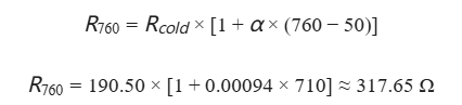
Judgment: Verify that even at the maximum temperature rise, the resistance increase will not reduce the ground fault current to a level that fails to trigger the protective relays.
Step 4: Auxiliary Equipment Verification
Current Transformer (CT) Test: Conduct a ratio and polarity test on the built-in CT (e.g., 20/5A); ensure the ratio error is less than 1%.
Mechanical Inspection: Inspect the spacing between the AISI-304 stainless steel resistor grids. Ensure the gaps are sufficient to prevent short-circuiting due to thermal expansion during the 10-second high-temperature surge.


CATEGORIES
- Neutral Grounding Resistor for Transformer
- Generator Neutral Grounding Resistor
- Low Voltage Neutral Grounding Resistor
- Neutral Grounding Arc Suppression Coils (Peterson Coil)
- Neutral Point Gap Grounding Protection Device
- Nitrogen Injection Fire Protection System for Transformer (NIFPS)
- Transformer Air-Cooled Control Equipment
- Nonlinear Neutral Grounding Equipment
LATEST NEWS
- Why Does the Neutral Point of a Large Generator Need to be Reliably Grounded?
- Transformer Neutral Grounding Methods and Applications for High-, Medium-, and Low-Voltage Systems
- How to Accurately Calculate the Neutral Grounding Resistance Value of a Transformer
- Global Top 8 Neutral Grounding Resistor (NGR)Manufacturers
- Neutral Grounding Resistor (NGR) Sizing – Step-by-Step Practical Guide
CONTACT US
WhatsApp: +86-18631228466
Tel: +86-312-5959618
Email: info@orionresistors.com
Add: No. 79, Fuchang Road, Zhongguancun Entrepreneurship Base, Baoding City,China