Solid, Resistance, and Ungrounded Systems — Which Is Safer for your Network?
Writer: admin Time:2025-09-13 20:01:53 Browse:708℃
In three-phase AC power systems, the way the neutral point is connected to ground is called the neutral grounding method.
It directly affects the safety, reliability, and economy of the grid, as well as equipment insulation levels, overvoltage control,
relay protection, and communication interference. In general, the grounding method of a power system is determined by
how transformer neutrals at various voltage levels are grounded. The main grounding modes include ungrounded,
arc-suppression coil grounding, low-resistance grounding, and direct grounding.
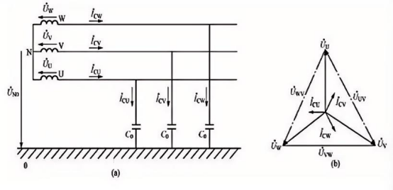
1. Ungrounded Neutral Systems
In an ideal ungrounded system, the phase-to-ground capacitive currents are equal and 120° apart, their vector sum equals
zero, and the neutral potential coincides with ground. However, if capacitances are unbalanced, neutral shift occurs. In such
systems, when a single-phase ground fault happens, the line-to-ground voltage of the two healthy phases rises to √3 times
the phase voltage, equivalent to line voltage. Although the system remains balanced and can continue operating temporarily,
the fault duration must not exceed two hours. Since the fault current is capacitive, arc grounding and dangerous overvoltages
may occur. Therefore, insulation monitoring or ground fault protection devices are usually required.
2. Arc-Suppression Coil Grounded Systems
To overcome the drawback of high fault current in ungrounded systems, arc-suppression coil grounding is applied. The coil,
a tunable reactor installed at the transformer or generator neutral, produces inductive current to counteract capacitive current
during a ground fault, thereby reducing or eliminating current at the fault point and extinguishing the arc. Compensation
modes include full, under, and over compensation, with overcompensation commonly adopted for safety margin.
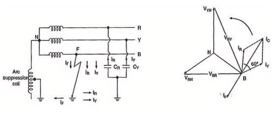
Above figure shows the 3-phase system employing Peterson coil grounding. Suppose line to ground fault occurs in the line B at point F.The fault current IF and capacitive currents IR and IY will flow as shown in figure. Note that IF flows through the Peterson coil (or Arc suppression coil) to neutral and back through the fault. The total capacitive current IC is the phasor sum of IR and IY as shown in phasor diagram in right figure. The voltage of the faulty phase is applied across the arc suppression coil. Therefore, fault current
IF lags the faulty phase voltage by 90°. The current IF is in phase opposition to capacitive current IC in right figure. By adjusting the tappings on the Peterson coil, the resultant current in the fault can be reduced, If inductance of the coil is so adjusted that IL = IC then resultant current in the fault will be zero.
3. Low-Resistance Grounded Systems
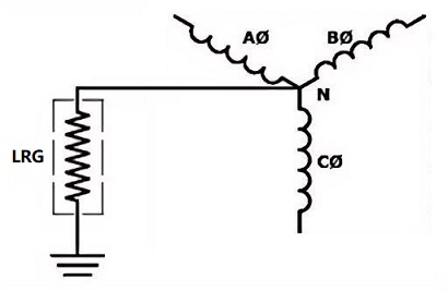
Low Resistance Grounding (LRG) connects a low-value resistor between the neutral point and ground, limiting single-phase fault current to tens or several hundred amperes. This prevents excessive fault current as seen in directly grounded systems, while ensuring that relays and automatic devices operate reliably to clear the fault. LRG also effectively suppresses arc overvoltages and reduces insulation stress. It is widely applied in 3–66 kV networks, particularly in industrial and local grids with high capacitive ground currents, offering a balanced solution combining safety, reliability, and economy.
4. Solid Grounded Systems
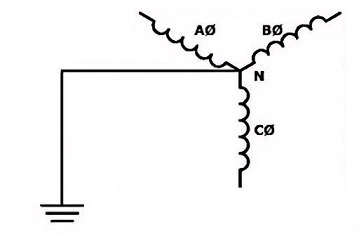
A solid grounded system is a type of grounding in which the neutral point of the power system is directly connected to the ground without any impedance to limit the fault current. During a single-phase ground fault, the large fault current allows protective devices to detect and quickly clear the fault. This method effectively stabilizes system voltages, reduces phase-to-phase overvoltages, and is suitable for low-voltage distribution systems (<1 kV) as well as high-voltage systems of 110 kV and above, especially in applications requiring fast protection and high safety.
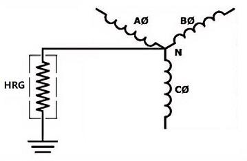
5. High-Resistance Grounded Systems:
High Resistance Grounding (HRG) is a method in which a high-value resistor is connected between the system neutral and ground, typically limiting the single-line-to-ground fault current to below 10A. Its main advantage is the effective suppression of arc-grounding overvoltages, reducing the risk of equipment damage, while allowing the system to continue operating with a ground fault for a certain period. This makes it particularly suitable for medium-voltage distribution systems (2.4kV–15kV) in industries such as petrochemical, steel, and paper, where continuous power supply is critical. However, HRG systems must be equipped with ground-fault detection and alarm devices, since prolonged undetected faults may escalate into more severe multi-phase faults. Overall, High Resistance Grounding achieves a balance between safety and continuous operation through a “soft grounding” approach.
The choice of neutral grounding method depends on system voltage: high-voltage systems above 220 kV typically use direct grounding, while 110 kV systems mainly adopt direct grounding with limited use of arc-suppression coils. Medium-voltage networks (20–60 kV) may use arc-suppression coil or ungrounded modes, preferring coil grounding when single-phase fault current exceeds 10 A. Lower-voltage systems (3–10 kV) are usually ungrounded, but arc-suppression coil or low-resistance grounding is applied if capacitive current exceeds 30 A.
For low-voltage networks below 1 kV, direct grounding ensures safety. In 220/380 V distribution systems, neutral grounding stabilizes line-to-ground voltages, reduces insulation requirements, mitigates overvoltage risks, and protects personnel and equipment. To further enhance safety, the neutral point, transformer tank, and surge arrester are often connected to a single grounding device, forming a “three-point common grounding” scheme that safeguards the system during faults or lightning events.
Low-voltage distribution → Solid Grounding
Medium-voltage continuous industrial systems → High Resistance Grounding (HRG)
Medium-voltage systems with conventional protection requirements → Low Resistance Grounding (LRG)
Large power networks with extensive overhead lines → Arc-suppression Coil Grounding (Petersen Coil)
Old systems or special cases → Ungrounded Neutral (gradually phased out or retrofitted)
Related Articles:
How to Accurately Calculate the Neutral Grounding Resistance Value of a Transformer
Global Top 8 Neutral Grounding Resistor (NGR)Manufacturers
Transformer Neutral Grounding Methods and Applications for High-, Medium-, and Low-Voltage Systems
Solid, Resistance, and Ungrounded Systems — Which Is Safer for your Network?
Why Does the Neutral Point of a Large Generator Need to be Reliably Grounded?


CATEGORIES
- Neutral Grounding Resistor for Transformer
- Generator Neutral Grounding Resistor
- Low Voltage Neutral Grounding Resistor
- Neutral Grounding Arc Suppression Coils (Peterson Coil)
- Neutral Point Gap Grounding Protection Device
- Nitrogen Injection Fire Protection System for Transformer (NIFPS)
- Transformer Air-Cooled Control Equipment
- Nonlinear Neutral Grounding Equipment
LATEST NEWS
- Why Does the Neutral Point of a Large Generator Need to be Reliably Grounded?
- Transformer Neutral Grounding Methods and Applications for High-, Medium-, and Low-Voltage Systems
- How to Accurately Calculate the Neutral Grounding Resistance Value of a Transformer
- Global Top 8 Neutral Grounding Resistor (NGR)Manufacturers
- Neutral Grounding Resistor (NGR) Sizing – Step-by-Step Practical Guide
CONTACT US
WhatsApp: +86-18631228466
Tel: +86-312-5959618
Email: info@orionresistors.com
Add: No. 79, Fuchang Road, Zhongguancun Entrepreneurship Base, Baoding City,China