Why 13.8kV Transformers and Generators Demand Different Grounding Method?
Writer: admin Time:2026-02-12 14:11:12 Browse:197℃
The 13.8kV level is a core voltage class within medium-voltage power systems, widely utilized in global industrial plants (such as paper mills and petrochemical plants), power plant auxiliary power systems, commercial park distribution networks, and various distributed energy projects. It serves as a critical hub connecting high-voltage transmission networks to low-voltage distribution systems and is a common voltage level for generator outlets and the low-voltage side of main transformers. In global grid architectures, the safe and stable operation of 13.8kV systems directly impacts the continuity of upstream and downstream power supply—requiring alignment with high-voltage grid standards while ensuring power reliability for terminal loads like motors and precision equipment.
As the "safety cornerstone" of a power system, the core role of a grounding system is to limit fault overvoltage, rapidly clear faults, and protect equipment insulation and personnel. Is there an ideal grounding method for transformers and generators in a 13.8kV system?
There is no "absolutely unified" ideal grounding method for 13.8kV systems. The selection must be adapted based on equipment type (transformer/generator), system structure (ratio of cables to overhead lines), load characteristics (importance and continuity requirements), and fault response needs. Generally, the optimal global solution is for transformers to prioritize "Low Resistance Grounding (LRG)" and for generators to prioritize "High Resistance Grounding (HRG)," with arc suppression coils used as a supplement in special scenarios.
The essence of power system grounding is to connect the equipment neutral point (or casing) to the earth via a conductor to form a fault current discharge path. These are categorized into "high-current grounding systems" (fault current ≥ 100 A) and "low-current grounding systems" (fault current < 100 A). The ideal grounding methods for 13.8kV systems revolve around these two categories, designed differentially based on the characteristics of transformers and generator
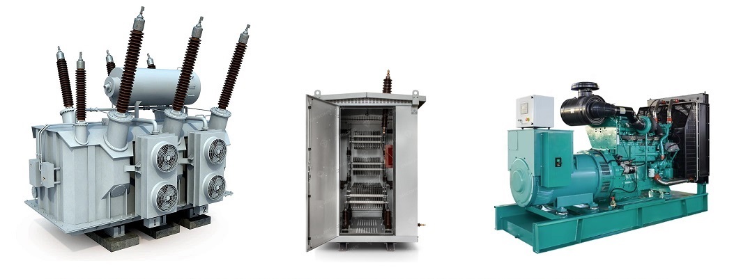
(I) Ideal Grounding for Transformers: Neutral Point via Low Resistance Grounding (High-Current)
1. Core Principle: The transformer neutral point is connected to the grounding grid through a low-value resistor (typically 10 to 80Omega, controlling fault current between 100A and 1000A). This is a typical application of a high-current grounding system. When a single-phase ground fault occurs, the fault current is rapidly discharged to the earth through the low resistor, creating a distinct short-circuit current. This triggers zero-sequence current protection devices to trip the fault line or equipment within tens of milliseconds, preventing the fault from escalating.
2.Key Advantages (Aligned with Global Requirements): First, it limits overvoltage levels; during a fault, the voltage rise of non-faulty phases generally does not exceed 1.4 times the phase voltage, reducing insulation requirements for windings and bushings and lowering equipment costs. Second, the relay protection is simple and reliable; the zero-sequence current signal is clear, eliminating the need for complex fault location devices and aligning with global industrial grid protection standards. Third, it avoids accidental arc overvoltage; the low resistance provides damping for transient overvoltages, protecting transformer insulation in cable-heavy 13.8kV scenarios. Fourth, the grounding grid design complies with international codes, allowing shared use with equipment casing and lightning protection grounding.
Case Study: Houston Petrochemical Complex, USA (Global Major Petrochemical Hub)In this complex, the 13.8kV main transformers (total capacity 120MVA) utilize Neutral Point Low Resistance Grounding (LRG) with a resistance value of 15Ω, limiting the fault current to 500A. With cables accounting for 90% of the network, the zero-sequence current protection can isolate fault circuits within 30ms during a single-phase ground fault. This prevents fault waves from affecting oil refining equipment and complies with the IEEE 141 standard and U.S. grid requirements for "rapid fault isolation" in industrial systems. To date, no transformer damage due to improper grounding has occurred.
(II) Ideal Grounding for Generators: Neutral Point via High Resistance Grounding (Low-Current)
1.Core Principle: The generator neutral point is connected to the grounding grid through a high-value resistor (often implemented via a distribution transformer with a secondary resistor, limiting fault current to 3A to 10A). This belongs to the low-current grounding system category. When a single-phase ground fault occurs in the generator stator winding, the high resistance limits the fault current to prevent it from exceeding 20A, which would otherwise melt the stator core (a critical component with extremely high repair costs). While the current is small, the fault is detected via zero-sequence voltage or current signals, allowing the system to operate with the fault for a short duration (1 to 2 hours) to ensure supply continuity.
2.Key Advantages (Aligned with Global Requirements): First, it protects core generator components; the low current prevents local overheating and burning of the stator core, fitting the standardized design of 13.8kV steam and hydro generators. Second, it ensures supply continuity, meeting the "non-stop" requirements of industrial plants (e.g., petrochemical or paper mills where sudden shutdowns cause massive losses). Third, it suppresses transient overvoltages; the high resistance damps arc overvoltages during faults, protecting the stator winding insulation and extending equipment life. Fourth, it suits distributed energy scenarios; using HRG at 13.8kV outlets avoids internal faults from impacting the grid side.
Case Study : Captive Power Plant of a Paper Mill in Finland (Global Large-Scale Paper Enterprise)Two 13.8kV steam turbine generators (capacity 30MVA each) utilize Neutral Point High Resistance Grounding (HRG) with a resistance value of 1000Ω, limiting fault current to 5A. Paper production requires continuous operation; if a generator trips due to a single-phase ground fault, the loss exceeds $100,000 per hour. The HRG scheme allows for "operation with fault for 1 hour," enabling maintenance personnel to locate the fault without interrupting production. This solution has become the universal grounding model for captive generators in paper mills worldwide.
(III) Special Scenario Supplement: Neutral Point via Arc Suppression Coil (Resonant Grounding)
1.Core Principle: In 13.8kV systems with a very high proportion of cable lines (such as urban industrial parks or data centers) where the capacitive fault current exceeds 30A, an arc suppression coil (adjustable inductor) is connected to the neutral point. It utilizes the inverse phase characteristic of inductive current relative to capacitive current to compensate for the fault current, reducing the current at the fault point to below 5A. This allows the arc to extinguish naturally and prevents phase-to-phase short circuits.
2.Application Prerequisite: This is used only as a supplemental solution and requires an automatic tuning device. it is adapted for 13.8kV scenarios requiring "high reliability + high cable ratio," such as industrial distribution networks in parts of Europe and semiconductor plant networks in the Asia-Pacific region.
Case Study: Changi Business Park, Singapore (Global High-End Commercial + Data Center Cluster)The 13.8kV transformer neutrals utilize a hybrid grounding method of "Low Resistance + Arc Suppression Coil" . With cables making up 95% of the network, the capacitive ground fault current reaches 50A. The arc suppression coil compensates this current to below 3A, preventing overvoltage caused by incomplete arc extinction. Simultaneously, the low resistor serves as backup protection; should the coil fail, the resistor rapidly discharges the fault current to trigger protection. This approach meets the "zero-outage, high-reliability" demands of high-end commercial parks by ensuring both continuity and safety.
Furthermore, regardless of the grounding method employed, the design must comply with unified global grounding grid standards. Priority should be given to utilizing natural grounding electrodes (such as reinforced concrete foundations and metal piping), combined with horizontal artificial grounding electrodes to form a grounding grid. This ensures that the grounding resistance meets stringent requirements (≤ 4Ω for transformers and ≤ 1Ω for generators), preventing safety hazards caused by poor grounding. These specifications constitute the core requirements of global power grids for 13.8kV system grounding.
CATEGORIES
- Neutral Grounding Resistor for Transformer
- Generator Neutral Grounding Resistor
- Low Voltage Neutral Grounding Resistor
- Neutral Grounding Arc Suppression Coils (Peterson Coil)
- Neutral Point Gap Grounding Protection Device
- Nitrogen Injection Fire Protection System for Transformer (NIFPS)
- Transformer Air-Cooled Control Equipment
- Nonlinear Neutral Grounding Equipment
LATEST NEWS
- Why Does the Neutral Point of a Large Generator Need to be Reliably Grounded?
- Transformer Neutral Grounding Methods and Applications for High-, Medium-, and Low-Voltage Systems
- How to Accurately Calculate the Neutral Grounding Resistance Value of a Transformer
- Global Top 8 Neutral Grounding Resistor (NGR)Manufacturers
- Neutral Grounding Resistor (NGR) Sizing – Step-by-Step Practical Guide
CONTACT US
WhatsApp: +86-18631228466
Tel: +86-312-5959618
Email: info@orionresistors.com
Add: No. 79, Fuchang Road, Zhongguancun Entrepreneurship Base, Baoding City,China