How to Size Arc-Suppression Coil (Petersen Coil) Grounding Systems?
Writer: admin Time:2026-06-05 18:03:17 Browse:170℃
1. System Overview & Operating Principle
An arc-suppression coil (ASC) grounding system is a low-current resonant grounding system. By connecting an inductive reactor with an adjustable iron core between the neutral point of a star-connected transformer/generator and earth, it utilizes inductive current to neutralize the distributed capacitive current flowing from the grid to the earth.
Normal Operation: The three-phase system is balanced. The neutral-to-earth displacement voltage (U0) is ≈0, and no current flows through the coil.
Single-Phase-to-Ground Fault: The faulted phase voltage drops to zero while healthy phase voltages rise to line-to-line voltage. The grid generates a capacitive fault current Ic (leading by 90o), and the neutral point induces an inductive current IL (lagging by 90o). Being 180o out of phase, Ic and IL counteract each other at the fault location, minimizing residual current and extinguishing the arc.
2. Sizing and Selection of Arc-Suppression Coils
Sizing centers entirely on evaluating the grid's total capacitive network current to earth (Ic).
A. Fundamental Calculation Formula
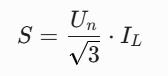
The rated capacity S (kVA) of an ASC is determined by the system rated line-to-line voltage Un (kV) and the required inductive current IL (A):
B. Determination of System Capacitive Current (Ic)
Field Measurement (Preferred): Measured directly under energized or outage states using the variable-frequency injection method.
Empirical Estimation (Design Phase):
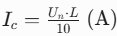
Overhead Lines:
 (where L is total line length in km)
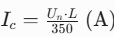
Cable Lines:
 (cable capacitance is typically 20–30 times higher than overhead lines)
C. Rated Current (IL) Safety Margin
To account for future grid expansions over the next 5–10 years, a safety margin factor of 1.25 to 1.35 must be included:
IL= (1.25 ~1.35) . Ic
D. Short-Time Thermal Rating (Operating Duration)
Standards mandate that the system must be allowed to run under single-phase fault conditions for 2 hours to locate the fault. Thus, the ASC must sustain continuous full-load operation for at least 2 hours without exceeding insulation temperature limits (typically Class F or H).
3. Compensation States: Mandatory Over-compensation
The relationship between IL and Ic dictates system safety:
Resonant Compensation (IL = Ic): [PROHIBITED] Causes series resonance, drastically amplifying the neutral displacement voltage and inducing severe overvoltages that destroy equipment.
Under-compensation (IL < Ic): [NOT RECOMMENDED] Disconnecting line segments can instantly drift the system into the resonant zone.
Over-compensation (IL > Ic): [INDUSTRIAL STANDARD] If lines are disconnected, the decrease in Ic moves the system further away from the resonance point, ensuring stability.
Critical Parameter: Degree of Detuning (v)
Industrial standards require the system to operate under over-compensation, maintaining a degree of detuning (v) at:
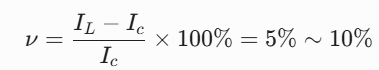
This limits the residual current at the fault point to 5A ~ 10A, ensuring arc self-extinction while safely preventing resonant overvoltages.
4. Comparison of Modern Automatic Tuning Technologies
Traditional fixed-tap coils have been replaced by automatic tracking resonant grounding compensation systems:
1. Biased Magnetic Type (Magnetic Valve ASC): Adjusts a DC excitation current to alter the core's magnetic permeability. Pros: Millisecond (ms) response, fully static solid-state control, high reliability. Cons: Introduces minor harmonics.
2. Turn-Modulation Type (On-Load Tap Changer ASC): Uses a motorized OLTC to switch winding physical taps based on pre-fault Ic measurements. Pros: Mature technology, zero harmonic distortion. Cons: Step-by-step discrete adjustment; cannot dynamically adjust during an active fault.
3. Phase-Controlled Type (TCR ASC): Controls the firing angle of anti-parallel thyristors (SCRs). Pros: Ultrafast dynamic response (< 20ms), continuous full-process transient compensation. Cons: High thermal dissipation, complex architecture, higher cost.
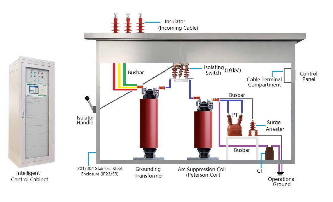
5. Engineering Essentials for Neutral Grounding Subsystems
1. Earthing Transformer: Required if the main power transformer uses a Delta (△) connection or lacks an accessible neutral. A ZN,yn (Zig-zag) configuration is highly recommended, as it presents near-zero impedance to zero-sequence currents, preventing localized overheating.
2. Damping Resistor: Connected in the ASC loop to suppress neutral displacement voltage during normal operations. Upon fault inception, the control system instantly shorts out this resistor via a fast bypass switch, releasing the ASC for full compensation.
3. Low-Current Fault Line Locator: Because the ASC reduces the fault current to a minimal value (< 10A), standard overcurrent protection relays fail. Modern systems integrate variable-frequency signal injection or transient traveling wave methods to capture transient characteristics at the exact millisecond of the fault, precisely identifying the faulted feeder to trigger an alarm.
CATEGORIES
- Neutral Grounding Resistor for Transformer
- Generator Neutral Grounding Resistor
- Low Voltage Neutral Grounding Resistor
- Neutral Grounding Arc Suppression Coils (Peterson Coil)
- Neutral Point Gap Grounding Protection Device
- Nitrogen Injection Fire Protection System for Transformer (NIFPS)
- Transformer Air-Cooled Control Equipment
- Nonlinear Neutral Grounding Equipment
LATEST NEWS
- Why Does the Neutral Point of a Large Generator Need to be Reliably Grounded?
- Transformer Neutral Grounding Methods and Applications for High-, Medium-, and Low-Voltage Systems
- How to Accurately Calculate the Neutral Grounding Resistance Value of a Transformer
- Global Top 8 Neutral Grounding Resistor (NGR)Manufacturers
- Neutral Grounding Resistor (NGR) Sizing – Step-by-Step Practical Guide
CONTACT US
WhatsApp: +86-18631228466
Tel: +86-312-5959618
Email: info@orionresistors.com
Add: No. 79, Fuchang Road, Zhongguancun Entrepreneurship Base, Baoding City,China