Neutral Grounding Resistor (NGR) Sizing – Step-by-Step Practical Guide
Writer: admin Time:2026-06-24 18:33:46 Browse:571℃
What is a Neutral Grounding Resistor (NGR)?
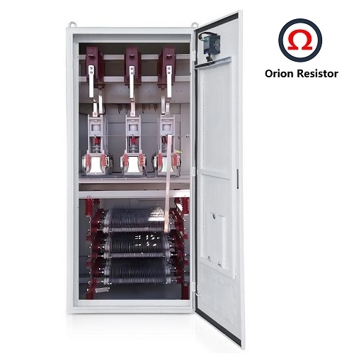
An NGR is connected between the transformer or generator neutral point and earth to:
✅ Limit earth fault current
✅ Control transient over-voltages
✅ Enable reliable earth fault detection
✅ Reduce mechanical & thermal stress on equipment
Inputs Required for NGR Sizing
Before starting calculations, ensure the following inputs are available:
➡️ Single Line Diagram (SLD)
➡️ Transformer / Generator Datasheet
➡️ Earthing Philosophy Document
▪️ Determines grounding type
▪️ Defines allowable earth fault current
➡️ Protection Philosophy / Relay Setting Philosophy
▪️ Earth fault current must be detectable by relays
➡️ Short Circuit Study Report
NGR sizing must always align with protection and earthing philosophy.
Selection of Resistance & Limited Earth Fault Current
The NGR resistance value shall be selected such that:
✔️ Earth fault current is high enough for selective and reliable relay operation
✔️ Earth fault current is low enough to minimize damage during fault conditions
Important Design Thumb Rule:
The limited earth fault current shall not exceed 50% of transformer/generator full load current
Step-by-Step Approach for NGR Sizing Calculations
Step-1: Calculate Phase-to-Neutral Voltage (Vph)
Vph=VLL / (√3)
VLL = Line-to-Line System Voltage
Step-2: Decide Earth Fault Current (Ief)
✔️ Based on relay sensitivity
✔️ Coordinated with protection philosophy
Typical values range from 100 A to 1000 A depending on system voltage and protection scheme
(Example: 400 A)
Step-3: Calculate NGR Resistance (RNGR)
Example:
System Voltage = 11 kV
Selected Earth Fault Current = 400 A
Vph=11000/√3=6350 V
Rngr=6350/400= 15.875 ohm
Step-4: Thermal Rating of NGR
NGR must withstand thermal stress during earth fault duration.
➡️ Power Dissipation (P)
P (Power Dissipation)=I 2×R
Energy=P×t
Select NGR time rating (e.g. 10 s / 30 s / 1 min) based on:
✔️ Relay operating time
✔️ Backup protection clearing time
Key Design Takeaways
✔️ NGR sizing is not only a calculation exercise, but a protection-driven design decision
✔️ Always align earthing philosophy + relay sensitivity + thermal limits
✔️ Incorrect NGR selection can cause:
❌ Relay mal-operation
❌ Excessive equipment damage
❌ Safety hazards
Good engineering = Balanced fault current + Reliable protection + Thermal safety
CATEGORIES
- Neutral Grounding Resistor for Transformer
- Generator Neutral Grounding Resistor
- Low Voltage Neutral Grounding Resistor
- Neutral Grounding Arc Suppression Coils (Peterson Coil)
- Neutral Point Gap Grounding Protection Device
- Nitrogen Injection Fire Protection System for Transformer (NIFPS)
- Transformer Air-Cooled Control Equipment
- Nonlinear Neutral Grounding Equipment
LATEST NEWS
- Why Does the Neutral Point of a Large Generator Need to be Reliably Grounded?
- Transformer Neutral Grounding Methods and Applications for High-, Medium-, and Low-Voltage Systems
- How to Accurately Calculate the Neutral Grounding Resistance Value of a Transformer
- Global Top 8 Neutral Grounding Resistor (NGR)Manufacturers
- What Are the Routine and Type Tests for a Transformer Neutral Grounding Resistor (NGR)?
CONTACT US
WhatsApp:
Tel: +86-312-5959618
Email: info@orionresistors.com
Add: No. 79, Fuchang Road, Zhongguancun Entrepreneurship Base, Baoding City,China