1 Minute to Calculate Neutral Grounding Resistors (6kV–35kV)
Writer: admin Time:2026-01-03 18:34:23 Browse:286℃
In medium-voltage (MV) power systems from 6 kV to 35 kV, the Neutral Grounding Resistor (NGR or NER) plays a critical role in system safety, overvoltage control, and protection coordination.
A properly designed NGR can suppress arcing ground overvoltage, limit earth fault current, and protect generators and transformers from severe damage.
This guide explains how to calculate neutral grounding resistance, choose the correct ground fault current, and define key technical parameters for reliable NGR selection.
What Is a Neutral Grounding Resistor (NGR)?
A Neutral Grounding Resistor is connected between the neutral point of a transformer or generator and ground to control single-line-to-ground fault current in MV systems.
Typical applications include:
1. 6.6 kV distribution networks
2. 10 kV industrial power systems
3. 11 kV utility feeders
4. 35 kV substation transformers
1. How to Calculate Neutral Grounding Resistance?
Core Design Principle: The resistive grounding current must be greater than the system capacitive ground current.
This ensures effective suppression of transient overvoltage during ground faults.
Neutral Grounding Resistor Formula
The resistance value is calculated using Ohm’s law:
R=U/I
Where:
R = Neutral grounding resistance (Ω)
U = Rated system line voltage (kV)
I = Ground fault current through the resistor (A)
2. How to Select Ground Fault Current (HRG vs LRG)
The selected grounding current depends on the earthing method and protection philosophy.
High Resistance Grounding (HRG)
1. Ground fault current: ≤ 10 A
2. Purpose: Suppress arcing ground overvoltage and allow continued operation under single-line-to-ground fault
3. Common in: Industrial plants and continuous process systems
Low Resistance Grounding (LRG)
1. Ground fault current: 100 A to 1000 A
2. Purpose: Ensure fast relay operation and clear ground faults quickly
3. Common in: Utility substations and Generator grounding systems
Engineering rule:
Grounding current I ≥ total system capacitive current (Ic)
3. Key Technical Parameters for NGR Design
3.1 Insulation Level and BIL
The insulation level of the NGR must match system voltage requirements.
a. Rated voltage: Phase voltage (U / √3)
b. Impulse withstand (BIL): According to IEEE 32 or IEC standards
Example for a 10 kV NGR:
a. Power-frequency withstand: 42 kV
b. Lightning impulse withstand: 75 kV
3.2 Temperature Rise and Time Rating
Ground faults generate significant heat in resistor elements.
Common time ratings: 10 seconds/ 30 seconds/ 60 seconds/ Continuous duty
| Application | Typical Time Rating |
|---|---|
| Low resistance grounding | 10 s / 30 s |
| High resistance grounding | Continuous |
Temperature rise limits (IEEE 32):
a. Stainless steel (short-time): up to 760°C
b. Continuous duty: typically ≤ 385°C
3.3 Neutral Grounding Resistor Material Selection
Material choice affects thermal stability, corrosion resistance, and service life.
1.Stainless steel (304 / 316 / 316L)
a.Most widely used
b.Stable resistance and good oxidation resistance
2.Nickel-chromium alloy (Cr20Ni80)
a.High-performance applications
b.Excellent corrosion resistance for coastal environments
3.Iron-chromium-aluminum (FeCrAl)
a. Cost-effective
b. Less suitable for extreme temperatures
3.4 IP Protection Class (Indoor vs Outdoor NGR)
| Installation Location | Typical IP Rating |
|---|---|
| Indoor NGR | IP20 / IP23 |
| Outdoor NGR | IP54 / IP55 |
Outdoor enclosures often use louvered panels and labyrinth ventilation to balance cooling and protection.
4. NGR Monitoring and Control Components
Modern neutral grounding resistor systems include intelligent monitoring:
1.Current Transformer (CT)
Measures ground fault current
2.Isolating switch or vacuum contactor
Allows maintenance disconnection
3.NGR Monitoring Unit
a. Resistance open-circuit detection
b. Temperature monitoring (PT100)
c. Ground fault event recording
These features significantly improve system reliability and safety.
5. Neutral Grounding Resistor Selection Table (Typical Values)
| System Voltage | Grounding Type | Ground Current | Typical Resistance | Material |
|---|---|---|---|---|
| 6.6 kV | LRG | 400 A | — | SS 304 |
| 10 kV | LRG | 200 A | — | SS 304 |
| 10 kV | HRG | 5 A | — | NiCr |
| 35 kV | LRG | 600 A | — | SS 316 |
6. How to Choose the Right NGR – Quick Checklist
1. Define grounding objective: alarm or trip
2. Calculate system capacitive current
3. Select grounding current (HRG or LRG)
4. Calculate resistance value
5. Confirm time rating and thermal capacity
6. Select enclosure IP rating
7. Add monitoring and protection accessories
Frequently Asked Questions
Q1: How do I calculate NGR resistance for a 10 kV system?
Use R = U / I, where U is system voltage and I is selected ground fault current.
Q2: What is the difference between HRG and LRG?
HRG limits current to a few amps for continuity; LRG allows higher current for fast fault clearing.
Q3: Why is neutral grounding resistor monitoring important?
An open-circuit NGR removes grounding protection and can cause dangerous overvoltage.
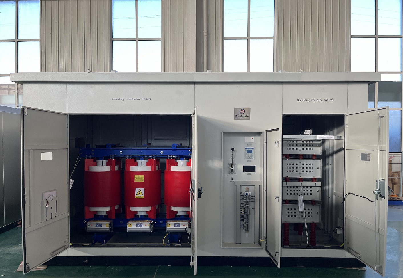
Detailed Calculation Example for Neutral Grounding Resistor (NGR) Selection
This example demonstrates how to select and calculate a Neutral Grounding Resistor (NGR) for a medium-voltage system, including resistance value, grounding current, thermal energy, and time rating.
1. System Data (Given Conditions)
Assume the following typical medium-voltage system:
a. System voltage: 10 kV (line-to-line)
b. System type: 3-phase, 50 Hz
c. Neutral grounding method: Low Resistance Grounding (LRG)
d. Fault clearing time: 10 seconds
e. Estimated capacitive ground current (Ic): 60 A
2. Selection of Ground Fault Current
Engineering Rule
To effectively suppress overvoltage:
I NGR ≥ IC
Selected Ground Fault Current
For reliable relay operation and margin:
Selected ground fault current:
I =200A
This value is commonly used in 10 kV LRG systems.
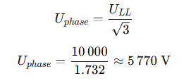
3. Calculation of Phase Voltage
Neutral grounding resistors are rated based on phase voltage, not line voltage.
4. Calculation of NGR Resistance Value
Using Ohm’s law:
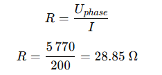
✅ Selected Resistance
R ≈ 29 Ω
5. Thermal Energy (kJ) Calculation
The resistor must safely absorb the thermal energy generated during a ground fault.
Formula
E=I2×R×t
Where:
I = grounding current (A)
R = resistance (Ω)
t = fault duration (s)
Calculation
E=2002×28.85×10E=11540000 JE=11540 kJ
✅ Required Thermal Capacity
≥ 11,540 kJ (10 s)
6. Time Rating Selection
Based on protection philosophy:
a. Low Resistance Grounding
b. Relay clearing time: < 10 s
✅ Selected Time Rating
10 seconds
(30 s can be selected for additional safety margin)
7. Resistor Material Selection
Based on thermal stress and environment:
1.Recommended material:
Stainless Steel 304 or 316
2. Advantages:
a. Stable resistance at high temperature
b. Good oxidation resistance
c. Long service life
8. Insulation Level Verification
For a 10 kV system, typical requirements are:
1. Rated voltage: 5.77 kV (phase voltage)
2. Power-frequency withstand: ≥ 42 kV
3. Lightning impulse withstand (BIL): ≥ 75 kV
Standards: IEEE 32 / IEC 60076 / IEC 61936
9. Enclosure and IP Rating
Assume outdoor installation:
1. Recommended IP rating: IP54 / IP55
2. Features:
a. Natural ventilation
b. Louvered or labyrinth airflow
c. Anti-corrosion coating
10. Final NGR Specification (Summary)
| Parameter | Value |
|---|---|
| System voltage | 10 kV |
| Grounding type | Low resistance |
| Ground fault current | 200 A |
| Resistance | ~29 Ω |
| Time rating | 10 s |
| Thermal capacity | ≥ 11,540 kJ |
| Material | Stainless steel 304/316 |
| Installation | Outdoor |
| IP rating | IP54 / IP55 |
| Standard | IEEE 32 / IEC |
Conclusion
This example shows that proper NGR selection requires:
1. Determining grounding philosophy (HRG or LRG)
2. Selecting grounding current based on capacitive current and protection needs
3. Calculating resistance using phase voltage
4. Verifying thermal energy and time rating
5. Confirming insulation level and enclosure design
CATEGORIES
- Neutral Grounding Resistor for Transformer
- Generator Neutral Grounding Resistor
- Low Voltage Neutral Grounding Resistor
- Neutral Grounding Arc Suppression Coils (Peterson Coil)
- Neutral Point Gap Grounding Protection Device
- Nitrogen Injection Fire Protection System for Transformer (NIFPS)
- Transformer Air-Cooled Control Equipment
- Nonlinear Neutral Grounding Equipment
LATEST NEWS
- Why Does the Neutral Point of a Large Generator Need to be Reliably Grounded?
- Transformer Neutral Grounding Methods and Applications for High-, Medium-, and Low-Voltage Systems
- How to Accurately Calculate the Neutral Grounding Resistance Value of a Transformer
- Global Top 8 Neutral Grounding Resistor (NGR)Manufacturers
- The Importance of Neutral Grounding Systems at a Glance
CONTACT US
WhatsApp: +86-18631228466
Tel: +86-312-5959618
Email: info@orionresistors.com
Add: No. 79, Fuchang Road, Zhongguancun Entrepreneurship Base, Baoding City,China