What Are the NGR Type Tests and Standards?
Writer: admin Time:2026-09-10 13:57:08 Browse:22℃
1. What Is a Neutral Grounding Resistor?
A Neutral Grounding Resistor (NGR) is connected between the neutral point of a transformer or generator and earth to limit the current flowing during a line-to-ground fault.
By limiting earth-fault current to a specified level, an NGR reduces thermal and mechanical stress on electrical equipment, limits damage at the fault location, and helps control transient overvoltages associated with earth faults.
NGRs are widely used in medium-voltage industrial power systems, substations, power plants, mining systems, and generator applications.
For international projects, the principal IEC standard specifically applicable to metallic neutral grounding resistors is IEC 60076-25:2023. IEEE projects may additionally refer to IEEE C57.32-2015 and IEEE C57.32a-2020, depending on the purchaser's technical specification and applicable project standards.
2. What Is an NGR Type Test?
A type test is performed on a representative NGR of a particular design and rating to demonstrate that the design can meet the specified electrical, thermal and mechanical requirements.
A type-test report is not automatically applicable to every NGR manufactured by the same supplier. Its applicability depends on the similarity of the subsequent product in terms of design, materials, dimensions, electrical rating, thermal characteristics and construction.
Where the design is sufficiently similar, previous type-test results may be used as design evidence, subject to the applicable standard, purchaser requirements and the manufacturer's documented assessment of design similarity.
Therefore, type testing is fundamentally a design verification activity, while routine testing is performed on individual manufactured units.
3. NGR Test Classification
According to IEC 60076-25:2023, NGR tests can be generally divided into three categories.
| Test Category | Typical Test | Purpose |
| Routine Test | Visual and dimensional inspection | Verify individual unit construction |
| Routine Test | Resistance measurement | Verify the specified resistance |
| Routine Test | Power-frequency withstand voltage | Verify insulation withstand capability |
| Routine Test | Insulation resistance | Verify insulation condition |
| Type Test | Temperature-rise test | Verify thermal performance of the design |
| Special Test | Inductance measurement | Determine impedance characteristics |
| Special Test | Lightning impulse test | Verify impulse withstand capability when specified |
| Special Test | Mechanical design verification | Verify mechanical integrity |
| Special Test | Degree of protection test | Verify the specified enclosure IP rating |
| Project-Specific Test | Seismic qualification | Verify seismic performance where required |
| Project-Specific Test | Environmental tests | Verify performance under specified environmental conditions |
| Project-Specific Test | Monitoring and communication tests | Verify auxiliary functions of the complete NGR assembly |
This classification is important because not every test performed on an NGR is a type test. In particular, IP testing, lightning impulse testing and inductance measurement should not be presented as mandatory type tests for every NGR unless specifically required by the applicable specification.

4. Routine Tests Performed on Each NGR
Routine tests are normally performed on each manufactured NGR before shipment.
4.1 Visual and Dimensional Inspection
The completed NGR is inspected for:
overall dimensions;
resistor element arrangement;
clearances and creepage distances;
electrical connections;
insulators and supports;
enclosure construction;
nameplate information;
grounding terminals;
ventilation openings; and
workmanship and general condition.
The purpose is to confirm that the manufactured unit conforms to the approved drawings and technical specification.
4.2 Resistance Measurement
The resistance of the NGR is measured and compared with the specified rated resistance and applicable tolerance.
Resistance should be evaluated with consideration of the resistor material and its temperature coefficient. For metallic resistor elements, the measured resistance varies with temperature.
4.3 Power-Frequency Withstand Voltage Test
The specified insulation system is subjected to the applicable power-frequency withstand voltage for the required duration.
The test verifies the dielectric strength between the relevant live parts and earth, and between electrically separated parts where applicable.
The test level is determined according to the applicable insulation requirements and project specification rather than being inferred solely from the system voltage.
4.4 Insulation Resistance Measurement
Insulation resistance is measured between the appropriate electrical circuits and earth or between isolated circuits.
The result provides a basic verification of the condition of insulation materials, supports and assembled components before shipment.
5. Type Test: Temperature-Rise Test
The temperature-rise test is the principal type test for an NGR under IEC 60076-25:2023.
The purpose is to demonstrate that the NGR design can withstand its specified operating duty without unacceptable thermal deterioration or loss of mechanical and electrical integrity.
The test must correspond to the NGR's specified duty.
For a rated-time-duty NGR, the representative unit is subjected to its specified rated current for its specified rated time.
For a continuous-duty NGR, the test arrangement and duration must reflect the continuous operating duty specified for the product.
During the test, temperatures at representative critical locations are monitored. Depending on the construction, these may include:
resistor elements;
electrical connections;
terminals;
supporting components;
insulating components; and
enclosure or other relevant locations.
After completion of the duty, the NGR is inspected for evidence of unacceptable thermal or mechanical deterioration. Relevant electrical characteristics may also be checked to verify that the resistor remains within the specified requirements.
The acceptance criteria should be based on the applicable edition of the standard and the approved technical specification rather than on an arbitrary universal resistance-change limit.
6. Example: 13.8 kV, 8 Ω, 1000 A, 15 s NGR
Consider an NGR with the following rating:
System voltage: 13.8 kV
Rated resistance: 8 Ω
Rated current: 1000 A
Rated time: 15 s
For a three-phase system, the phase-to-neutral voltage is approximately:
13.8 kV / √3 = 7.97 kV
The corresponding ground-fault current is approximately:
7.97 kV / 8 Ω ≈ 996 A
which is approximately the specified 1000 A rating.
For the temperature-rise type test, the representative NGR is therefore subjected to its rated duty of 1000 A for 15 s, provided that these are the manufacturer's specified rated current and rated time.
Temperature data are recorded during the test and the NGR is inspected after the test for unacceptable thermal or mechanical deterioration.
The post-test electrical characteristics can also be verified to assess the condition of the resistor following the specified thermal duty.
7. Special Test: Inductance Measurement
Although an NGR is fundamentally designed to provide resistive impedance, the physical arrangement of resistor elements, connecting conductors and enclosure components can result in a certain amount of inductance.
Inductance measurement is classified as a special test under IEC 60076-25:2023.
Where specified, the inductance of the complete NGR assembly can be measured and documented.
The measured impedance characteristics may be useful for:
grounding-system studies;
fault-current calculations;
transient analysis;
protection coordination; and
system modelling.
The measured inductance should therefore be treated as a documented design characteristic rather than automatically as a mandatory type-test requirement for every NGR.
8. Special Test: Lightning Impulse Test
A lightning impulse test may be specified where the NGR's insulation system requires verification against impulse overvoltages.
The test voltage should be selected according to the specified insulation level and the applicable insulation-coordination requirements.
It should not be assumed that a 13.8 kV system automatically requires a particular impulse voltage such as 75 kV.
The applicable impulse withstand level depends on the specified insulation system, system conditions, equipment arrangement and project requirements.
Where required, the test is performed with the specified impulse waveform, polarity and number of impulses, and the results are evaluated according to the applicable standard.
9. Special Test: Mechanical Design Verification
The NGR must remain mechanically stable during transportation, handling and service.
Mechanical design verification may be performed where specified by the purchaser or project.
The verification can address:
resistor element supports;
insulators;
mounting structures;
electrical connections;
enclosure structure;
lifting arrangements;
fastening systems; and
other mechanically significant components.
The objective is to demonstrate that the NGR maintains its structural and electrical integrity under the specified mechanical conditions.
Where seismic performance is required, seismic qualification should be performed according to the applicable project specification and seismic standard.
10. Special Test: Enclosure Degree of Protection
The enclosure degree of protection may be verified according to the specified IP rating and the applicable enclosure protection standard.
For outdoor NGR installations, the enclosure must provide an appropriate balance between environmental protection and heat dissipation.
Unlike a fully sealed low-power electrical enclosure, an NGR generates significant heat during fault-current operation. Ventilation openings are therefore an important part of the thermal design.
An IP rating such as IP23, IP40, IP54 or another specified level should therefore be selected according to:
installation location;
environmental conditions;
required protection against solid objects and water;
cooling requirements; and
purchaser specifications.
IP verification should be treated as a special or project-specific test, rather than as a universal NGR type test.
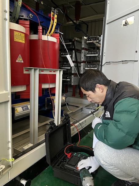
11. Environmental and Seismic Verification
Environmental tests such as humidity, vibration, corrosion or other climatic tests may be required for specific applications.
These tests are not universal type tests for every NGR under IEC 60076-25:2023.
They may instead be specified according to:
installation environment;
transportation requirements;
seismic zone;
offshore or coastal conditions;
mining applications;
outdoor exposure; or
purchaser-specific specifications.
For equipment installed in high-seismic areas, the NGR structure, resistor elements, insulators and connections may require specific seismic verification.
12. Monitoring and Protection Functions
Modern NGR assemblies may include temperature sensors, neutral-point voltage monitoring, resistor continuity monitoring, alarm contacts, local indication and communication interfaces.
These functions should be verified as part of the complete NGR assembly when specified.
Typical functional checks include:
resistor overtemperature alarm;
temperature sensor operation;
neutral-point voltage alarm;
resistor continuity or failure detection;
local alarm indication;
remote alarm contacts;
communication interface;
SCADA signals; and
fault simulation and alarm logic.
These functional tests should not be described as core NGR type tests under IEC 60076-25:2023. They are normally project-specific functional verification of the auxiliary monitoring and control system.

13. What Happens After the Type Test?
After successful completion of the applicable type test, the manufacturer obtains documented evidence that the tested design satisfies the relevant requirements.
For subsequent units manufactured to the same or sufficiently similar design, the existing type-test report may be used as design verification evidence, provided that the similarity assessment is acceptable to the applicable standard and purchaser.
However, every production unit should still undergo the required routine tests.
This distinction is fundamental:
Type test verifies the design.
Routine test verifies the individual manufactured unit.
A successful type test therefore does not replace routine testing on subsequent NGRs.
14. Recommended International NGR Test Structure
For an international NGR technical specification or product datasheet, the following structure is recommended:
Routine Tests — Each NGR
Visual and dimensional inspection
Rated resistance measurement
Power-frequency withstand voltage test
Insulation resistance measurement
Type Test — Representative Design
Temperature-rise test
Special Tests — When Specified
Inductance measurement
Lightning impulse test
Mechanical design verification
Degree of protection test
Project-Specific Verification — When Applicable
Seismic qualification
Environmental testing
Monitoring and protection functional testing
Communication and SCADA verification
15. Conclusion
A reliable NGR is not demonstrated by resistance measurement alone. Its design must withstand the specified earth-fault duty while maintaining its electrical, thermal, mechanical and insulation integrity.
For international projects, IEC 60076-25:2023 provides the key IEC framework for neutral grounding resistors. IEEE C57.32 and C57.32a-2020 may be applied where required by the project or purchaser.
The most important distinction is between Routine Tests, Type Tests and Special Tests.
For the NGR itself, the temperature-rise test is the principal type-test verification of thermal performance. Resistance measurement, power-frequency withstand and insulation resistance are routine tests performed on individual units, while inductance, lightning impulse, mechanical design, IP protection and other environmental or functional verifications are normally specified as special or project-specific tests.
This test structure provides a clearer and more internationally defensible basis for NGR design verification, manufacturing quality control and customer acceptance.
CATEGORIES
- Neutral Grounding Resistor for Transformer
- Generator Neutral Grounding Resistor
- Low Voltage Neutral Grounding Resistor
- Neutral Grounding Arc Suppression Coils (Peterson Coil)
- Neutral Point Gap Grounding Protection Device
- Nitrogen Injection Fire Protection System for Transformer (NIFPS)
- Transformer Air-Cooled Control Equipment
- Nonlinear Neutral Grounding Equipment
LATEST NEWS
- Why Does the Neutral Point of a Large Generator Need to be Reliably Grounded?
- Transformer Neutral Grounding Methods and Applications for High-, Medium-, and Low-Voltage Systems
- How to Accurately Calculate the Neutral Grounding Resistance Value of a Transformer
- Global Top 8 Neutral Grounding Resistor (NGR)Manufacturers
- How to Accurately Select the Insulation Level of a Neutral Grounding Resistor?
CONTACT US
WhatsApp:
Tel: +86-312-5959618
Email: info@orionresistors.com
Add: No. 79, Fuchang Road, Zhongguancun Entrepreneurship Base, Baoding City,China