How to Accurately Select the Insulation Level of a Neutral Grounding Resistor?
Writer: admin Time:2026-09-10 14:32:29 Browse:23℃
NGR Insulation Levels: Standards, Selection and Testing
Neutral grounding resistors (NGRs) are widely used in transformer and generator grounding systems to limit ground-fault current and reduce damage to windings, cores, cables, and other electrical equipment.
The insulation level of an NGR is an important part of its electrical design. It determines the required withstand voltage, insulation coordination, electrical clearance, creepage distance, and dielectric test requirements.
For international projects, NGR insulation should not be selected simply according to the system line voltage. The NGR rated voltage, applicable standards, system configuration, altitude, environmental conditions, and project requirements must all be considered.
1. What Is the Insulation Level of an NGR?
The insulation level of an NGR defines the voltage stresses that its insulation system is designed to withstand without electrical breakdown.
Typical insulation-related requirements include:
Power-frequency withstand voltage
Lightning impulse withstand voltage
Insulation resistance
Electrical clearance
Creepage distance
Insulation coordination
Environmental and altitude requirements
For an NGR directly connected between a transformer or generator neutral point and earth, the voltage across the resistor during a ground fault is primarily related to the system phase-to-neutral voltage.
Therefore, the NGR insulation rating should not automatically be equated with the system line-to-line voltage.
2. Which Standards Apply to NGR Insulation?
The following international standards may be relevant to NGR insulation design and testing:
Standard | Main Application |
IEC 60076-25:2023 | Dry-type neutral grounding resistors |
IEC 60071-1:2019 | Insulation coordination |
IEC 60071-2 | Application guidance for insulation coordination |
IEC 60664-1 | Insulation coordination for low-voltage equipment |
IEC 60076-3 | Transformer insulation and dielectric tests |
IEEE C57.32 / IEEE C57.32a | Neutral grounding devices and related requirements where specified |
For dry-type NGRs, IEC 60076-25:2023 is the most directly applicable IEC product standard.
The purchaser's specification should also be reviewed because additional or project-specific tests may be required.
3. How Is the NGR Rated Voltage Calculated?
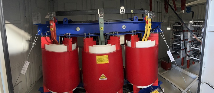
For an NGR directly connected between the system neutral and earth, IEC 60076-25:2023 uses the phase-to-neutral voltage as the basis for determining the NGR rated voltage.
The basic relationship is:Ur = U / √3
Where:
Ur = NGR rated voltage
U = system nominal line-to-line voltage
For example, for a 13.8 kV system:
Ur = 13.8 kV / √3
Ur = 7.97 kV
The calculated NGR rated voltage is then used to select the applicable standard insulation level.
IEC 60076-25:2023 specifies that the selected Um should be equal to or higher than the calculated NGR rated voltage:
Um ≥ Ur
Therefore, for a 13.8 kV system:
Ur = 7.97 kV
The next applicable standard value is:
Um = 12 kV
Accordingly, the corresponding insulation values are:
Power-frequency withstand voltage: 28 kV RMS
Lightning impulse withstand voltage: 75 kV peak
Minimum air clearance: 120 mm
This is an important distinction when specifying NGR insulation for medium-voltage systems.
4. NGR Insulation Level Selection Table
The following table applies the IEC 60076-25:2023 selection principle:
Ur = U / √3
and then selects the next standard Um satisfying:
Um ≥ Ur
For systems below 1,000 V, IEC 60076-25:2023 refers to IEC 60664-1 for the applicable insulation coordination approach. Therefore, LV systems should not automatically be assigned the medium-voltage insulation values from the IEC 60076-25 table.
System Voltage U | NGR Rated Voltage Ur | Selected Um | Power-Frequency Withstand Ud | Lightning Impulse Withstand Up | Minimum Air Clearance |
0.380 kV | 0.219 kV | LV | See IEC 60664-1 | See IEC 60664-1 | Project dependent |
0.400 kV | 0.231 kV | LV | See IEC 60664-1 | See IEC 60664-1 | Project dependent |
0.415 kV | 0.240 kV | LV | See IEC 60664-1 | See IEC 60664-1 | Project dependent |
0.480 kV | 0.277 kV | LV | See IEC 60664-1 | See IEC 60664-1 | Project dependent |
0.600 kV | 0.346 kV | LV | See IEC 60664-1 | See IEC 60664-1 | Project dependent |
0.690 kV | 0.398 kV | LV | See IEC 60664-1 | See IEC 60664-1 | Project dependent |
1.200 kV | 0.693 kV | 1.0 kV | 2.2 kV RMS | 12 kV peak | 14 mm |
2.400 kV | 1.386 kV | 3.6 kV | 10 kV RMS | 40 kV peak | 60 mm |
3.300 kV | 1.905 kV | 3.6 kV | 10 kV RMS | 40 kV peak | 60 mm |
3.600 kV | 2.078 kV | 3.6 kV | 10 kV RMS | 40 kV peak | 60 mm |
4.160 kV | 2.402 kV | 3.6 kV | 10 kV RMS | 40 kV peak | 60 mm |
6.300 kV | 3.637 kV | 7.2 kV | 20 kV RMS | 60 kV peak | 90 mm |
6.600 kV | 3.811 kV | 7.2 kV | 20 kV RMS | 60 kV peak | 90 mm |
7.200 kV | 4.157 kV | 7.2 kV | 20 kV RMS | 60 kV peak | 90 mm |
10.000 kV | 5.774 kV | 7.2 kV | 20 kV RMS | 60 kV peak | 90 mm |
11.000 kV | 6.351 kV | 7.2 kV | 20 kV RMS | 60 kV peak | 90 mm |
13.800 kV | 7.967 kV | 12 kV | 28 kV RMS | 75 kV peak | 120 mm |
14.400 kV | 8.314 kV | 12 kV | 28 kV RMS | 75 kV peak | 120 mm |
14.760 kV | 8.521 kV | 12 kV | 28 kV RMS | 75 kV peak | 120 mm |
15.000 kV | 8.660 kV | 12 kV | 28 kV RMS | 75 kV peak | 120 mm |
20.000 kV | 11.547 kV | 12 kV | 28 kV RMS | 75 kV peak | 120 mm |
22.000 kV | 12.702 kV | 17.5 kV | 38 kV RMS | 95 kV peak | 160 mm |
27.600 kV | 15.935 kV | 17.5 kV | 38 kV RMS | 95 kV peak | 160 mm |
34.500 kV | 19.919 kV | 24 kV | 50 kV RMS | 125 kV peak | 220 mm |
44.000 kV | 25.403 kV | 36 kV | 70 kV RMS | 170 kV peak | 320 mm |
66.000 kV | 38.105 kV | 52 kV | 95 kV RMS | 250 kV peak | 480 mm |
These values provide a useful reference for NGR insulation selection. The final design should always be verified against the applicable standard and project specification.
5. Standard NGR Insulation Levels
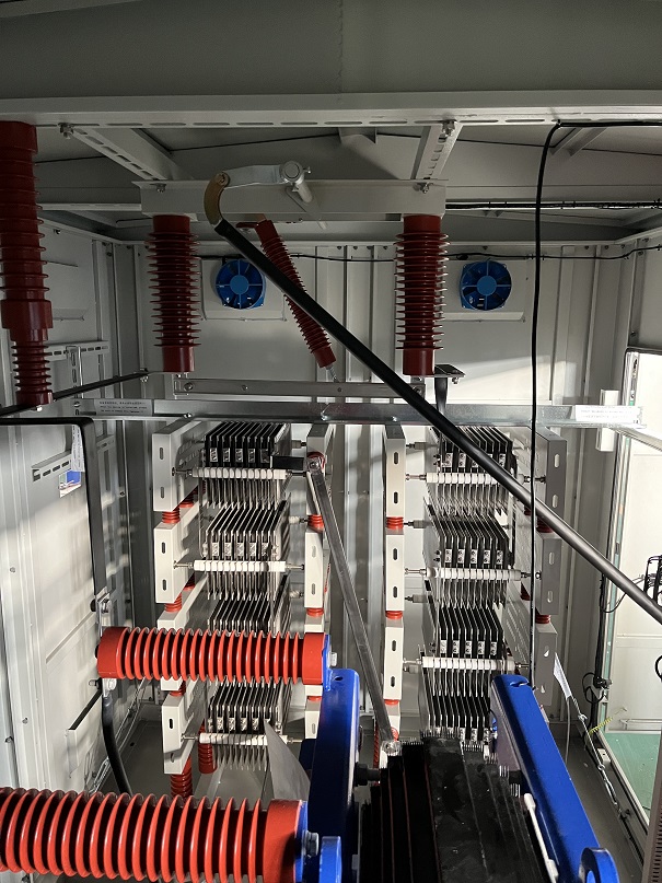
IEC 60076-25:2023 provides standardized insulation levels for NGRs.The principal values include:
Um | Power-Frequency Withstand Ud | Lightning Impulse Withstand Up | Minimum Air Clearance |
1.0 kV | 2.2 kV RMS | 12 kV peak | 14 mm |
3.6 kV | 10 kV RMS | 40 kV peak | 60 mm |
7.2 kV | 20 kV RMS | 60 kV peak | 90 mm |
12 kV | 28 kV RMS | 75 kV peak | 120 mm |
17.5 kV | 38 kV RMS | 95 kV peak | 160 mm |
24 kV | 50 kV RMS | 125 kV peak | 220 mm |
36 kV | 70 kV RMS | 170 kV peak | 320 mm |
52 kV | 95 kV RMS | 250 kV peak | 480 mm |
72.5 kV | 140 kV RMS | 325 kV peak | 630 mm |
100 kV | 185 kV RMS | 450 kV peak | 900 mm |
123 kV | 230 kV RMS | 550 kV peak | 1100 mm |
145 kV | 275 kV RMS | 650 kV peak | 1300 mm |
170 kV | 325 kV RMS | 750 kV peak | 1500 mm |
245 kV | 460 kV RMS | 1050 kV peak | 2100 mm |
One important point is that Um in IEC 60076-25:2023 has an NGR-specific definition. It should not automatically be interpreted in exactly the same way as Um in other high-voltage equipment standards.
6. Example: 13.8 kV, 8 Ω, 1000 A NGR
Consider a neutral grounding resistor with the following specification:
Parameter | Value |
System voltage | 13.8 kV |
NGR current | 1,000 A |
NGR resistance | 8 Ω |
Fault duration | 15 s |
First calculate the NGR rated voltage:
Ur = U / √3
Ur = 13.8 kV / √3
Ur = 7.97 kV
The selected standard insulation level must satisfy:
Um ≥ Ur
Therefore:
Um = 12 kV
The corresponding IEC 60076-25:2023 insulation values are:
Parameter | Value |
Selected Um | 12 kV |
Power-frequency withstand Ud | 12 kV RMS |
Lightning impulse withstand Up | 75 kV peak |
Minimum air clearance | 120 mm |
The required resistance can be calculated from the phase-to-neutral voltage and the specified fault current:
R = Ur / I
Therefore:
R = 7.97 kV / 1,000 A
R ≈ 7.97 Ω
If the specified NGR resistance is 8 Ω, the actual fault current is approximately:
I = Ur / R
I = 7.97 kV / 8 Ω
I ≈ 996 A
This is consistent with a nominal 1,000 A NGR, subject to the specified resistance tolerance and actual system conditions.

7. Insulation Resistance Test
Insulation resistance measurement is part of the routine test program for NGRs covered by IEC 60076-25:2023.
The test verifies the insulation condition between electrically live components and grounded components.
Typical measurement points may include:
NGR terminals to enclosure
Live resistor elements to earth
Insulated supports to grounded components
Neutral terminals to the enclosure
The actual test voltage and acceptance criterion should be specified according to the applicable standard and project requirements.
It is therefore not technically appropriate to state that every NGR must use a 2,500 V insulation resistance tester and achieve a universal minimum value such as 100 MΩ.
The correct acceptance criterion depends on the equipment design, applicable standard, manufacturer specification, and purchaser requirements.
8. Power-Frequency Withstand Voltage Test
The power-frequency withstand test verifies that the NGR insulation can withstand the specified AC test voltage without breakdown or flashover.
For example, if:
Um = 12 kV
the corresponding power-frequency withstand voltage is:
Ud = 28 kV RMS
The test is normally applied between the appropriate insulated electrical parts and earth or enclosure according to the standard test arrangement.
The test evaluates the integrity of:
Insulated neutral terminals
Terminal bushings
Insulated supports
Internal insulation
Barriers
Electrical connections
Insulation between energized components and the enclosure
The exact test duration and acceptance requirements should follow the applicable standard.
9. Lightning Impulse Withstand Test
Lightning impulse testing verifies the ability of the NGR insulation system to withstand transient overvoltages.
For:
Um = 12 kV
the corresponding lightning impulse withstand level is:
Up = 75 kV peak
However, lightning impulse testing should not be described as a mandatory routine test for every NGR.
Under IEC 60076-25:2023, lightning impulse testing is classified as a special test.
It may be required when specified by:
The purchaser
The project technical specification
The insulation coordination study
The system voltage level
The installation environment
The applicable utility standard
10. Electrical Clearance and Creepage Distance
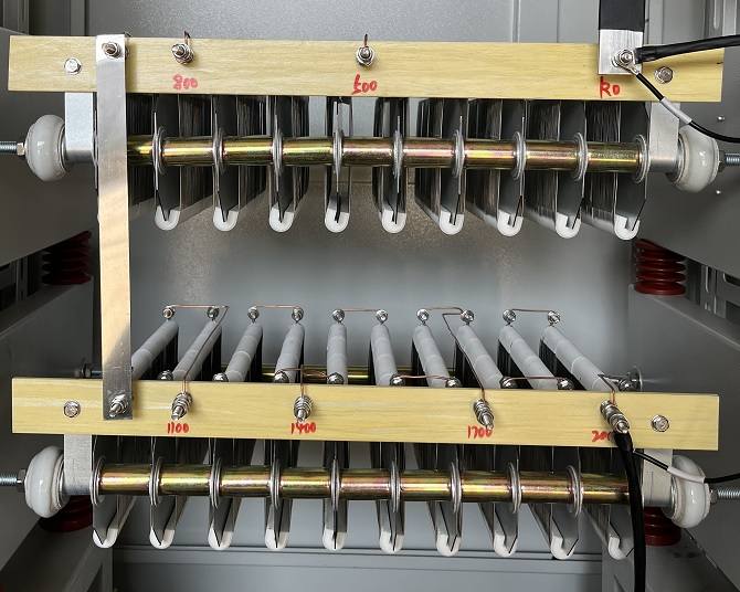
Electrical clearance is the shortest distance through air between conductive parts at different electrical potentials.
Creepage distance is the shortest distance along the surface of an insulating material.
Both parameters are important in NGR design.
For example, when:
Um = 12 kV
IEC 60076-25:2023 specifies a minimum air clearance of:
120 mm
However, the final design may require a larger clearance depending on:
Installation altitude
Pollution level
Indoor or outdoor installation
Humidity
Insulating material
Surface contamination
Transient overvoltage
Project requirements
Therefore, the standard minimum clearance should not automatically be treated as the final physical dimension of every NGR enclosure.
11. Altitude and Environmental Conditions
Altitude affects the dielectric strength of air.
As altitude increases, the insulation strength of air decreases. Consequently, equipment installed at high altitude may require increased electrical clearance or other insulation coordination measures.
For installations above 1,000 m, the insulation requirements should be evaluated using the applicable guidance in IEC 60071-2.
An NGR installed at a high-altitude power plant may therefore require:
Increased air clearance
Increased creepage distance
Higher insulation level
Modified enclosure construction
Additional environmental protection
The installation altitude should therefore be clearly stated in the NGR technical specification.
12. NGR Insulation Tests and Test Classification
IEC 60076-25:2023 separates NGR tests into routine tests, type tests, and special tests.
Test | Classification |
Visual and dimensional inspection | Routine Test |
Rated resistance measurement | Routine Test |
Power-frequency withstand voltage test | Routine Test |
Insulation resistance measurement | Routine Test |
Temperature-rise test | Type Test |
Inductance measurement | Special Test |
Lightning impulse test | Special Test |
Mechanical design verification | Special Test |
Degree-of-protection test | Special Test |
This classification is important when preparing a factory test plan.
For example, lightning impulse testing and IP degree-of-protection testing should not automatically be presented as mandatory type tests for every NGR.
They are special tests under IEC 60076-25:2023 and should be included when required by the project or purchaser.
13. Temperature Rise and NGR Insulation Design
The insulation system of an NGR is closely related to its thermal design.
During a ground fault, the resistor elements can reach a high temperature depending on the fault current and duration.
IEC 60076-25:2023 specifies maximum temperature-rise values for resistive elements according to the operating duty:
NGR Duty | Maximum Temperature Rise of Resistive Elements |
Rated time ≤ 60 s | 760 K |
Extended time < 10 min | 610 K |
Continuous duty | 385 K |
Temperature rise and absolute temperature are different concepts.
For example:
ΔT = 760 K
means a temperature rise of 760 K above the reference temperature. It does not mean that the resistor element is operating at exactly 760 °C.
The actual element temperature depends on the initial temperature and operating conditions.
NGR thermal design should consider:
Resistor element material
Resistance value
Fault current
Fault duration
Thermal capacity
Ventilation
Enclosure construction
Insulating materials
Terminal temperature
Adjacent component temperature
Electrical insulation and thermal performance should therefore be evaluated together.
14. What About 380 V to 690 V NGRs?
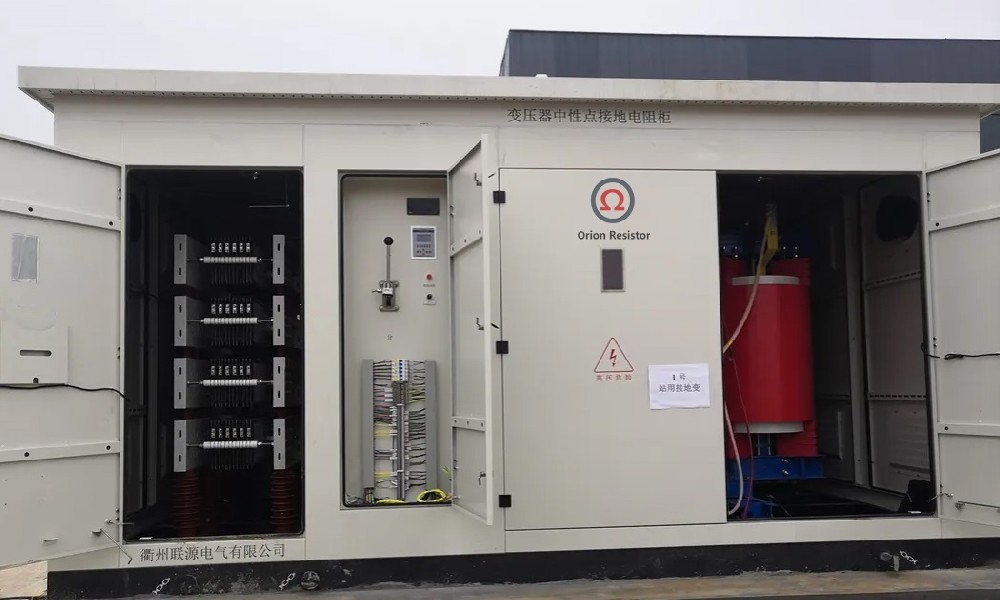
Low-voltage NGRs are used in applications such as:
Generator auxiliary systems
Industrial power systems
Mining power systems
Motor systems
Plant auxiliary transformers
Low-voltage generator systems
Common system voltages include:
System Voltage | Equivalent in kV |
380 V | 0.380 kV |
400 V | 0.400 kV |
415 V | 0.415 kV |
480 V | 0.480 kV |
600 V | 0.600 kV |
690 V | 0.690 kV |
These systems are below 1,000 V.
Therefore, the insulation coordination approach should consider IEC 60664-1 and the actual low-voltage equipment design rather than directly applying the medium-voltage insulation table from IEC 60076-25:2023.
For example, for a 400 V system:
Ur = 400 V / √3
Ur ≈ 231 V
This calculation does not mean that the NGR should automatically be assigned the 1.0 kV insulation level from the IEC 60076-25 table.
The final insulation design depends on factors such as:
Overvoltage category
Pollution degree
Clearance
Creepage distance
Insulation material
Working voltage
Transient overvoltage
Equipment construction
Applicable project requirements
15. Practical NGR Insulation Selection Procedure
A practical engineering procedure can be summarized as follows.
Step 1: Determine the system voltage
Identify the nominal line-to-line system voltage.
Example:
U = 13.8 kV
Step 2: Calculate the NGR rated voltage
For a directly connected neutral grounding resistor:
Ur = U / √3
Therefore:
Ur = 13.8 / √3 = 7.97 kV
Step 3: Identify the applicable standard
For a dry-type NGR, check IEC 60076-25:2023.
For systems below 1,000 V, also consider IEC 60664-1 and the applicable low-voltage requirements.
Step 4: Select the standard Um
Select the next standard value satisfying:
Um ≥ Ur
For a 13.8 kV system:
Ur = 7.97 kV
Therefore:
Um = 12 kV
Step 5: Determine the withstand levels
For Um = 12 kV:
Ud = 28 kV RMS
Up = 75 kV peak
Step 6: Check electrical clearance
For Um = 12 kV:
Minimum air clearance = 120 mm
Then determine whether additional clearance or creepage distance is required.
Step 7: Review environmental conditions
Check:
Installation altitude
Indoor or outdoor installation
Pollution level
Ambient temperature
Humidity
Seismic requirements where applicable
Step 8: Define the factory test program
Separate the tests into:
Routine Tests
Type Tests
Special Tests
This approach provides a clearer and more defensible technical specification for an NGR.
16. Common Mistakes in NGR Insulation Selection
Mistake 1: Using the system line voltage directly
An incorrect approach would be:
13.8 kV system → 13.8 kV NGR rated voltage
For a directly connected NGR, the initial calculation is:
Ur = 13.8 / √3 = 7.97 kV
The appropriate standard Um is then selected based on:
Um ≥ Ur
which gives:
Um = 12 kV
Mistake 2: Treating lightning impulse testing as a routine test
Lightning impulse testing is a special test under IEC 60076-25:2023.
It should be specified when required by the project or insulation coordination requirements.
Mistake 3: Applying one insulation resistance limit to every NGR
A universal requirement such as:
Insulation resistance ≥ 100 MΩ
should not be presented as an IEC 60076-25 requirement for every NGR.
The test voltage and acceptance criterion should be established according to the applicable standard and project specification.
Mistake 4: Ignoring altitude
Air insulation strength decreases with increasing altitude.
High-altitude installations may therefore require additional insulation coordination measures.
Mistake 5: Confusing resistance tolerance with temperature-related resistance change
The rated resistance tolerance and the resistance change caused by heating are different technical requirements.
For example, an NGR may have a specified rated resistance tolerance:
R ± 10%
while its resistance variation during the temperature-rise test is evaluated separately.
These two requirements should not be treated as the same parameter.
17. Conclusion
NGR insulation selection should be based on the actual neutral-to-earth voltage, the applicable product standard, insulation coordination, and installation conditions.
For a directly connected NGR covered by IEC 60076-25:2023, the basic relationship is:
Ur = U / √3
The calculated Ur is then used to select the next applicable standard value satisfying:
Um ≥ Ur
For example, for a 13.8 kV system:
Ur = 13.8 / √3 = 7.97 kV
Therefore:
Um = 12 kV
The corresponding insulation levels are:
Ud = 28 kV RMS
Up = 75 kV peak
Minimum air clearance = 120 mm
For low-voltage systems such as 380 V, 400 V, 415 V, 480 V, 600 V, and 690 V, the insulation coordination approach should consider IEC 60664-1 and the actual equipment design rather than directly applying the medium-voltage NGR insulation table.
A properly designed NGR should integrate electrical, thermal, mechanical, environmental, and insulation requirements. Selecting the insulation level from the system voltage alone is not sufficient for a reliable international NGR specification.
CATEGORIES
- Neutral Grounding Resistor for Transformer
- Generator Neutral Grounding Resistor
- Low Voltage Neutral Grounding Resistor
- Neutral Grounding Arc Suppression Coils (Peterson Coil)
- Neutral Point Gap Grounding Protection Device
- Nitrogen Injection Fire Protection System for Transformer (NIFPS)
- Transformer Air-Cooled Control Equipment
- Nonlinear Neutral Grounding Equipment
LATEST NEWS
- Why Does the Neutral Point of a Large Generator Need to be Reliably Grounded?
- Transformer Neutral Grounding Methods and Applications for High-, Medium-, and Low-Voltage Systems
- How to Accurately Calculate the Neutral Grounding Resistance Value of a Transformer
- Global Top 8 Neutral Grounding Resistor (NGR)Manufacturers
- How to Accurately Select the Insulation Level of a Neutral Grounding Resistor?
CONTACT US
WhatsApp:
Tel: +86-312-5959618
Email: info@orionresistors.com
Add: No. 79, Fuchang Road, Zhongguancun Entrepreneurship Base, Baoding City,China