IEEE C57.32 vs. IEC 60076-25: Which NGR Standard Does Your Project Actually Need?
Writer: admin Time:2026-09-17 09:58:30 Browse:272℃
1. Introduction: Industry Background & The Strategic Value of Standardization
In modern medium- and high-voltage power networks, the neutral point treatment of transformers and generators dictates the safety, reliability, and continuous operation of the power system. Neutral Grounding Resistors (NGRs)—also referred to as Neutral Earthing Resistors (NERs)—serve as critical protection hardware engineered to connect between the system neutral point and earth ground.
The primary engineering objectives of an NGR include:
1.Fault Current Limitation: Controlling single-phase-to-ground fault currents (Ig) to predefined safety levels, preventing thermal and mechanical destruction of phase conductors, transformer windings, and generator stator cores.
2.Transient Overvoltage Suppression: Damping arcing ground transient overvoltages that can otherwise escalate to multi-phase insulation flashovers across the network.
3.Protective Relay Coordination: Providing sufficient ground-fault current to trigger selective directional ground-fault relays (e.g., ANSI 50N/51N, 67N) for rapid fault isolation.
4.Ensuring Personnel and Asset Safety: Minimizing Step and Touch voltages around substation earthing grids during active fault conditions.
As global energy infrastructure expands across interconnected markets, engineering procurement and construction (EPC) contractors face a complex regulatory landscape. Today, two major standardization bodies govern NGR design, manufacturing, and validation: the Institute of Electrical and Electronics Engineers (IEEE) and the International Electrotechnical Commission (IEC). Operating under distinct philosophies, IEEE and IEC standards dictate different testing methodologies, thermal limits, and mechanical designs. Ensuring full compliance with these standards is critical to avoiding project delays, equipment failure, or regulatory rejection during field commissioning.
2. Overview of International NGR Standard Systems
The deployment of IEEE versus IEC standards depends heavily on regional power grid heritage, local electrical codes, and project specifications.
IEEE Standard Hierarchy
Dominates North America (United States, Canada, Mexico), parts of South America, Saudi Arabia, and offshore oil and gas sectors adhering to ANSI/NEMA engineering paradigms.
IEC Standard Hierarchy
Prevalent across Europe, Asia-Pacific, the Middle East, Africa, and Latin America, serving as the default benchmark for cross-border utility and industrial developments.

Core Strategic Orientations
IEC 60076-25:2023 (Power Transformers – Part 25: Neutral Grounding Resistors)
Prior to 2023, IEC lacked a dedicated single-point standard for NGRs, relying instead on a patchwork of generic transformer and resistor standards. The release of IEC 60076-25:2023 established a unified international code focusing on detailed equipment design criteria, material performance, thermodynamic response under fault conditions, standardized integration with auxiliary assets, harmonic current derating, and environmental operating classifications.
IEEE C57.32-2015 / C57.32a-2020 (IEEE Standard for Requirements, Terminology, and Test Procedures for Neutral Grounding Devices)
Historically established as the global benchmark for grounding devices, the IEEE C57.32 series approaches equipment compliance from a system-level perspective. It defines standard duty cycles, precise definitions, application guidelines, factory production tests, design tests, and field commissioning verification protocols, aligning closely with North American safety codes (NEC/NFPA 70) and NEMA enclosure classifications.
Equipment Applicability Scope
Both standard families cover dry-type, naturally ventilated or forced-air cooled NGR systems connected to the neutral points of:
1.Three-phase power transformers (Wye/Star windings or Zig-zag grounding transformers).
2.Medium-voltage synchronous generators and motors.
3.Neutral derivation equipment in industrial distribution networks (1.2kV to 76.5kV).
3. Normative Standards Cross-Reference Matrix
The technical design and component selection of an NGR system require compliance with specific standards governing resistors, insulation, protection, and enclosure assemblies. The table below outlines the governing standards for each critical technical subsystem within a compliant NGR assembly, reconciling North American (IEEE) and International (IEC) requirements.
| Subsystem / Item | Technical Scope & Engineering Objective | Applicable IEEE / ANSI Standard | Applicable IEC Standard |
| Overall NGR System Design | Terminology, rating requirements, short-time capability, design and field testing procedures | IEEE C57.32-2015 / C57.32a-2020 | IEC 60076-25:2023 |
| Resistor Elements / Banks | Alloy composition, resistance tolerances (±10%), temperature rise limits, thermal mass calculations | IEEE C57.32-2015 (Sections 4 & 5) | IEC 60076-25:2023 (Clause 5 & 6) |
| Insulation Coordination | Creepage distance, clear air clearances, power-frequency and impulse withstand voltages | IEEE C57.19.01 / IEEE 142 | IEC 60071-1:2019 / IEC 60071-2:2023 |
| Insulating Bushings | Outdoor/indoor high-voltage insulated bushings for AC applications above 1000V | IEEE C57.19.00 / IEEE C57.19.01 | IEC 60137:2017 |
| Vacuum Contactors / Switches | Vacuum bypass contactors, ground disconnectors, and isolation switching devices | ANSI C37.66 / IEEE C37.20.2 | IEC 62271-106:2021 / IEC 62271-102:2018 |
| Post Insulators | Indoor/outdoor ceramic, glass, or composite post insulators supporting resistor banks | ANSI C29.10 / ANSI C29.17 | IEC 60273:1990 / IEC 62231:2006 |
| Current Transformers (CT) | Neutral line CTs for ground fault detection, relaying, and metering | IEEE C57.13-2016 | IEC 61869-1:2023 / IEC 61869-2:2012 |
| Insulator Mechanical Testing | Mechanical cantilever, tensile, and electrical flashover testing of support insulators | ANSI C29.1 | IEC 60168:1994 + AMD2:2000 |
| Switchgear & Enclosure Assembly | Sheet metal enclosure structural integrity, ventilation louvers, lifting lugs, and earthing bus | NEMA 250 / IEEE C37.20.1 | IEC 62271-200:2021 |
| Ingress Protection (IP Rating) | Environmental protection against water entry, solid objects, and foreign body penetration | NEMA 250 (Type 1, 3R, 4, 4X) | IEC 60529:1989+AMD2:2013 (IP Code) |

4. In-Depth Analysis of Standard Technical Execution Rules
To ensure compliance during production and acceptance, engineering teams must evaluate five core technical dimensions governed by IEEE C57.32 and IEC 60076-25.
4.1 Scope of Application and Device Definitions
Both IEEE C57.32 and IEC 60076-25 restrict their primary scope to dry-type air-cooled neutral grounding devices installed in medium-voltage distribution and transmission networks (1.2kV to 76.5kV).
Transformer Neutral Application: Installed between the neutral point of a star-connected transformer winding (or neutral coupler / zig-zag transformer) and ground. The NGR must withstand system line-to-ground voltage during a full phase-to-ground fault.
Generator Neutral Application: Installed at the synchronous generator neutral. Must account for continuous third-harmonic currents (180Hz in 60Hz systems; 150Hz in 50 Hz systems) produced by non-sinusoidal winding flux distributions, which induce steady-state parasitic thermal loading.
4.2 Rated Electrical Parameters & Operating Tolerances
Proper selection of an NGR relies on defining four core parameters:
Rated Voltage (Vn) = VLL/ √3
Target Fault Current (In) = Vn / R0
(Where VLL represents line-to-line system nominal voltage, and R0 is cold neutral resistance at 20℃.)
Resistance Tolerance: Both IEEE C57.32 and IEC 60076-25 enforce a strict nominal cold resistance tolerance of ±10% at 20℃. For high-precision applications, a tolerance of ±5% can be requested.
Rated Short-Time Duration (t):
IEEE C57.32 Classifications: 10 seconds, 1 minute, 10 minutes, and Extended/Continuous. The 10-second rating is standard for Low-Resistance Grounding (LRG) systems where automatic protection trips isolate faults under 1.0 second.
IEC 60076-25 Classifications: Standardized durations of 10 seconds, 30 seconds, 60 seconds, or Continuous. IEC projects frequently specify a 30-second duration for industrial plant backup protection coordination.
Continuous Current Rating ( Icont ): IEEE C57.32 requires LRG resistors to withstand a steady-state neutral imbalance current equal to at least 10% of their rated short-time fault current indefinitely, or up to 90 A continuous without exceeding continuous thermal rise limits. IEC 60076-25 requires explicit specification of steady-state neutral current induced by line-to-ground capacitive unbalance and generator third-harmonic currents.
4.3 Material Metallurgy, Insulation, and Structural Design
The thermal performance of an NGR depends on its resistive element material. Standard commercial grades include Stainless Steel 304 (Cr18Ni9), Stainless Steel 430 (Cr17 ferritic steel), and Nickel-Chromium alloys (Ni80Cr20).
Resistance increases as the element heats up during a fault. The instantaneous resistance R(T) at elevated temperature T is calculated using the material temperature coefficient α:
R(T) = R20 . [ 1 + α. (T - 20) ]
To maintain sufficient ground-fault current to trip protective relays at the end of the fault duration, high positive temperature coefficient alloys must be derated. IEEE C57.32 and IEC 60076-25 cap the maximum allowable temperature rises based on element metallurgy:
| Resistor Material | IEEE C57.32 Short-Time (10s) | IEC 60076-25 Short-Time (10s/30s) | Continuous Duty Limit |
| Stainless Steel Alloys (SS304/SS430) | 760℃ | 610℃ - 760℃ | 380℃ |
| NiCr / High Temperature Alloys | 760℃ (Standard cap) | 760℃ | 380℃ |
| Cast Iron Elements (Legacy) | 510℃ | Not Recommended | 260℃ |
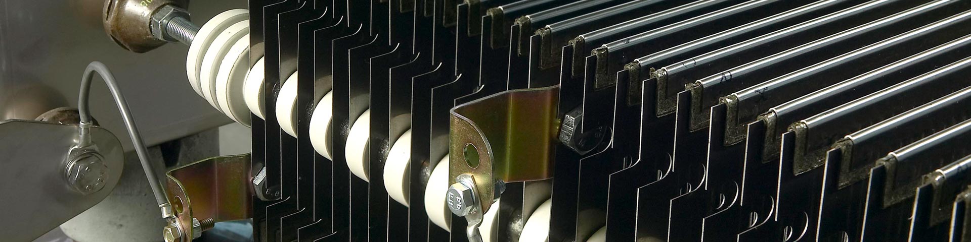
Dry-type NGRs rely primarily on natural convection cooling (AN). Louvers must encourage bottom-to-top airflow while preventing foreign object ingress. Mounting brackets must use slotted slide channels or floating rod suspensions to prevent element sagging or phase-to-ground flashovers under maximum thermal expansion.

4.4 Insulation Levels and Enclosure Protection (IP vs. NEMA)
System insulation coordination must adhere to IEC 60071-1 or IEEE C57.19.01. The internal insulation class (post insulators, support rods, bushings) must match or exceed the system nominal voltage rating (Vsystem) and Lightning Impulse Withstand Voltage (BIL).
| Environmental Operating Conditions | Equivalent NEMA Rating | IEC 60529 IP Rating | Mechanical Ventilation Strategy |
| Indoor Substation Rooms | NEMA Type 1 | IP20 / IP21 | Open mesh / Natural convection louvers |
| Outdoor Substation (Standard) | NEMA Type 3R | IP23 / IP33 | Rainproof angled downward louvers |
| Dusty / Desert Environments | NEMA Type 3S / 4 | IP54 | Filtered louvers with forced thermal derating |
| Coastal / Highly Polluted / Chemical | NEMA Type 4X (SS316L) | IP55 / IP65 | Fully sealed enclosure with internal convection channels |
Note: Increasing the IP rating reduces natural convective airflow, requiring larger internal spatial clearance and higher thermal element mass to absorb adiabatic heat during short-time faults.
4.5 Factory Inspection & Acceptance Testing Requirements
Compliance testing ensures the mechanical, electrical, and thermal performance of an NGR assembly. Tests are categorized into Routine Factory Tests (performed on 100% of manufactured units) and Design / Type Tests (performed on a representative unit to validate a product line).
| Test Category | Test Description | Execution Protocol & Acceptance Criteria (IEEE C57.32 & IEC 60076-25) |
| Routine Test | Cold Resistance Measurement | Measured at ambient temperature; converted to 20°C equivalent. Measured value must lie strictly within ±10% of nameplate R0. |
| Routine Test | Applied Power-Frequency Voltage Test | High voltage applied between resistor element assembly and grounded enclosure for 60 seconds. Pass criteria: No insulation breakdown or flashover. |
| Routine Test | CT Verification | Instrument Transformer ratio, polarity, and winding resistance verified per IEC 61869-2 / IEEE C57.13. |
| Type Test | Temperature Rise Test | Resistor is subjected to rated fault current (In) for rated short-time duration (t). Temperature rise measured via infrared thermography or embedded thermocouples. Pass criteria: Max temperature rise must not exceed 760°C (IEEE) or 610°C–760°C (IEC). |
| Type Test | Lightning Impulse Withstand (BIL) | Full 1.2/50μs wave impulse applied across terminal bushings to earth ground. Pass criteria: Three consecutive pulses applied without flashover or insulation breakdown. |
| Type Test | Short-Time Withstand Capability | Verifies mechanical rigidity under high magnetic forces during initial asymmetrical fault current peaks (Ipeak = 2.55 In). Pass criteria: No permanent structural deformation, element contact, or mechanical failure. |
5. Engineering Selection Guidelines & Field Execution
Deploying an NGR successfully requires matching the standard to the project geography, network configuration, and site conditions.
5.1 Standard Selection Strategy
Utility Grids in Europe, Asia-Pacific, Middle East, Africa: Specify IEC 60076-25:2023 as the primary equipment standard. Ensure all auxiliary components (CTs, post insulators, bushings) carry corresponding IEC certification marks.
North American & ANSI-Centric Markets: Specify IEEE C57.32-2015/2020. Ensure enclosure compliance aligns with NEMA 250 standards and that internal structural clearances adhere to ANSI/IEEE clearance tables.
Cross-Border Infrastructure & Hybrid EPC Projects: Specify a dual-standard manufacturing design: structure and temperature rise limits designed to satisfy IEC 60076-25 (providing conservative thermal margins), while testing protocols and continuous current withstand are executed in compliance with IEEE C57.32 routine and type testing methodologies.
5.2 Common Engineering Selection Errors
Ignoring Generator Third-Harmonic Heating: Installing a standard transformer-duty NGR on a generator neutral without accounting for continuous circulating third-harmonic currents (150/180Hz). Mitigation: Size the continuous current rating (Icont) to accommodate harmonic distortion without exceeding 380℃ continuous rise limits.
Over-specifying Protection Class (IP Rating) Without Thermal Derating: Ordering an IP65 enclosure for an outdoor LRG unit without increasing the internal grid element thermal capacity. High enclosure protection limits natural convection, causing severe overheating during short-time faults.
Improper Thermal Drift Calculations in Protection Relaying: Selecting an alloy with a high temperature coefficient (α) without calculating the final fault current (Ifinal) at peak operating temperature (760℃). If current drops below the pickup setting of downstream ground fault relays (51N), protection coordination will fail.
6. Conclusion
Neutral Grounding Resistors are essential protection assets in modern industrial and utility power distribution. Selecting and manufacturing NGRs in strict compliance with IEEE C57.32 and IEC 60076-25:2023 ensures these units operate predictably under severe system line-to-ground faults.
By aligning material metallurgy, thermal rise limits, ingress protection, and rigorous factory type testing with international standards, power systems engineers and equipment manufacturers can eliminate application blind spots, streamline field commissioning, and maintain grid stability worldwide.

CATEGORIES
- Neutral Grounding Resistor for Transformer
- Generator Neutral Grounding Resistor
- Low Voltage Neutral Grounding Resistor
- Neutral Grounding Arc Suppression Coils (Peterson Coil)
- Neutral Point Gap Grounding Protection Device
- Nitrogen Injection Fire Protection System for Transformer (NIFPS)
- Transformer Air-Cooled Control Equipment
- Nonlinear Neutral Grounding Equipment
LATEST NEWS
- Why Does the Neutral Point of a Large Generator Need to be Reliably Grounded?
- Transformer Neutral Grounding Methods and Applications for High-, Medium-, and Low-Voltage Systems
- How to Accurately Calculate the Neutral Grounding Resistance Value of a Transformer
- Global Top 8 Neutral Grounding Resistor (NGR)Manufacturers
- What Are the Routine and Type Tests for a Transformer Neutral Grounding Resistor (NGR)?
CONTACT US
WhatsApp:
Tel: +86-312-5959618
Email: info@orionresistors.com
Add: No. 79, Fuchang Road, Zhongguancun Entrepreneurship Base, Baoding City,China