How to accurately calculate the neutral grounding resistance(NGR) for 3.3kV, 4.16kV, and 6.6kV systems?
Writer: admin Time:2026-01-30 14:53:03 Browse:2686℃
In industrial medium voltage (MV) distribution networks—specifically 3.3kV, 4.16kV, and 6.6kV systems—the method of system grounding is a pivotal factor in determining operational reliability and equipment longevity. High Resistance Grounding (HRG), typically designed to limit ground fault current to 10A, has become the industry benchmark for mining, petrochemical, and captive power plant environments.
1. The Strategic Role of HRG in Industrial MV Systems
Medium voltage systems are the backbone of heavy industry. Unlike solidly grounded systems, which experience catastrophic damage during a single-phase-to-ground fault, or ungrounded systems, which are prone to transient overvoltages and "arcing grounds," a 10A HRG system provides a "best-of-both-worlds" scenario.
The primary objectives of the 10A NGR are:
a.Limitation of Mechanical and Thermal Stress: By restricting the fault to 10A, the energy at the fault point (I2rt) is minimized, preventing the melting of motor laminations or transformer windings.
b.Transient Overvoltage Suppression: It provides a discharge path for the system's capacitive charge, limiting transient overvoltages to approximately 2.5 times nominal peak voltage, whereas ungrounded systems can see excursions exceeding 6 times.
c.Selectivity and Continuity: A 10A current is sufficiently high to be detected by sensitive Zero-Sequence (Core-Balance) Current Transformers (CTs), allowing for "alarm-only" or "selective tripping" schemes that maintain production continuity.
2. Fundamental Mathematical Calculations
2.1 The Ohmic Value (R)
The calculation of the resistance value is deceptively simple but requires high precision. The resistor must be sized based on the system phase-to-neutral voltage.
The core formula is:
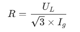
Where:
UL = Nominal Line-to-Line Voltage (V)
Ig = Target Ground Fault Current (10A)
For the three standard voltages, the theoretical values at 20°C are:
3.3 kV System: R = 1905V / 10A = 190.5 Ω
4.16 kV System: R = 2402V / 10A = 240.2 Ω
6.6 kV System: R = 3811V / 10A = 381.1 Ω
2.2 The Impact of Temperature and Material
Engineering reality dictates that the resistor will heat up during a fault. Most NGRs use stainless steel alloys (e.g., Grade 304 or Alchrome). These materials have a positive temperature coefficient (α). As the resistor temperature rises from 20°C to 300°C or 500°C during a fault, the resistance increases, which subsequently decreases the fault current.
To ensure the fault current does not drop below the trip threshold of the protective relays, a "cold" resistance margin of 5%–10% is often subtracted, or the material is specified to have a low coefficient of expansion to keep Ig within ± 10% of the 10A target across the entire thermal cycle.
2.3 System Capacitive Charging Current (Ic0)
A critical rule in HRG design is: INGR ≥ Ic0.
Every cable, motor winding, and surge capacitor in the system contributes to the total phase-to-ground capacitance. In a ground fault, this capacitance discharges. If the NGR current is lower than the charging current, the system behaves like an ungrounded system, risking resonance. For 3.3kV–6.6kV systems, Ic0 typically ranges from 1A to 5A per 1000kVA of installed capacity. A 10A NGR is usually sufficient for most industrial plants, but for sprawling networks with extensive cabling, Ic0 must be measured or calculated to ensure the 10A setting remains dominant.
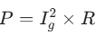
3. Thermal Rating and Power Considerations
Unlike transformers, NGRs are not always rated for continuous duty. The power rating is defined by:
3.1 Short-Time vs. Continuous Rating
Short-Time Rating (10s/30s/60s): This is the standard for systems designed to trip on the first fault. Since the fault is cleared in milliseconds, a 10-second rating provides a massive safety margin.
Continuous Rating: Required if the system is designed to "alarm and leave" (allow the fault to persist until a scheduled shutdown). For a 6.6kV/10A system, the resistor must dissipate ≈38 kW continuously. This requires significant ventilation and high-mass resistor elements to prevent burnout.
3.2 Comparison Table of Typical Specs
| System Voltage (kV) | Line-to-Neutral (V) | Calculated R (Ω) | Recommended Power (10s) |
| 3.3 | 1905 | 191 | 25 - 30 kW |
| 4.16 | 2402 | 240 | 35 - 40 kW |
| 6.6 | 3811 | 381 | 55 - 65 kW |
4. Application Case Studies
Case A: 6.6kV Petrochemical Distribution
In a 2500kVA transformer application, the focus is on transformer protection. A 381Ω NGR was deployed. During a cable insulation failure, the NGR limited the current to 10.03A. The Zero-Sequence relay detected this via a 50/5 CT and tripped the feeder breaker in 400ms. Because the current was limited to 10A, the "point of fault" damage was negligible—a small char mark on the cable rather than a vaporized conductor. This saved the company an estimated $200,000 in transformer repair costs.
Case B: 4.16kV Generator Protection
For a 3000kW synchronous generator, the stator core is the most expensive component. High ground fault currents can melt the stator iron, requiring a total rewind or replacement. By using a 240Ω NGR, the generator is protected against internal ground faults. The NGR was paired with a 59N (Neutral Overvoltage) relay. When a fault occurred in the terminal box, the NGR kept the current at 10A, allowing a controlled ramp-down of the turbine, preventing a catastrophic "instantaneous" mechanical shock to the shaft.
5. The Evolution: Smart NGR Systems
Modern power systems demand more than a "passive box of wires." The integration of "Smart NGR" features has revolutionized maintenance:
Active Monitoring: Real-time tracking of neutral voltage (Un) and leakage current (In). An unexpected rise in In (e.g., to 2A) can signal deteriorating insulation before a full 10A fault occurs.
Continuity Detection: One of the biggest risks is an "open" NGR. If the resistor grid breaks, the system becomes ungrounded without the operator knowing. Smart NGRs inject a small signal or use a "monitor relay" to ensure the neutral-to-ground path is intact.
Thermal Protection: PT100 sensors within the resistor bank can trigger an upstream trip if the resistor exceeds its design temperature (e.g., 380°C), protecting the NGR housing and nearby equipment.
Harmonic Filtration: In systems with heavy VFD (Variable Frequency Drive) loads, 3rd harmonics can circulate through the neutral. Modern NGR designs account for this extra heating and may include filtering to prevent nuisance alarms.
The selection of a 10A Neutral Grounding Resistor for 3.3kV, 4.16kV, and 6.6kV systems is a critical engineering decision that balances protection and continuity. By utilizing the precise R = Uph / Ig calculation, accounting for the system's inherent capacitance, and selecting appropriate thermal ratings, engineers can virtually eliminate the risk of catastrophic ground fault damage. As industry 4.0 progresses, the transition from passive resistors to intelligent, monitored NGR assemblies will be the standard for ensuring the resilience of the global power infrastructure.
CATEGORIES
- Neutral Grounding Resistor for Transformer
- Generator Neutral Grounding Resistor
- Low Voltage Neutral Grounding Resistor
- Neutral Grounding Arc Suppression Coils (Peterson Coil)
- Neutral Point Gap Grounding Protection Device
- Nitrogen Injection Fire Protection System for Transformer (NIFPS)
- Transformer Air-Cooled Control Equipment
- Nonlinear Neutral Grounding Equipment
LATEST NEWS
- Why Does the Neutral Point of a Large Generator Need to be Reliably Grounded?
- Transformer Neutral Grounding Methods and Applications for High-, Medium-, and Low-Voltage Systems
- How to Accurately Calculate the Neutral Grounding Resistance Value of a Transformer
- Global Top 8 Neutral Grounding Resistor (NGR)Manufacturers
- Neutral Grounding Resistor (NGR) Sizing – Step-by-Step Practical Guide
CONTACT US
WhatsApp: +86-18631228466
Tel: +86-312-5959618
Email: info@orionresistors.com
Add: No. 79, Fuchang Road, Zhongguancun Entrepreneurship Base, Baoding City,China