How to accurately calculate a 10 A neutral grounding resistor for a 13.8 kV system?
Writer: admin Time:2026-01-25 15:17:37 Browse:397℃
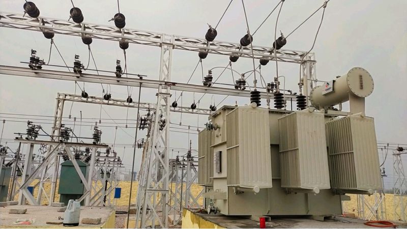
In a 13.8 kV medium-voltage distribution system, the Neutral Grounding Resistor (NGR) is a critical component for ensuring safe and stable system operation. Its fundamental purpose is to intentionally introduce a grounding resistance at the system neutral, thereby limiting single line-to-ground fault current to a controlled and acceptable level.
The NGR is typically installed between the system neutral point and earth and can be flexibly applied to different system configurations, including transformer-grounded and generator-grounded systems. It provides multiple functions, such as fault current limitation, equipment protection, and continuity of power supply.
Functions and Value of Neutral Grounding Resistors
From a functional perspective, the primary role of an NGR is to limit single line-to-ground fault current, commonly to a preset value such as 10 A, thereby reducing arc energy at the fault point and preventing arcing ground overvoltages that could damage insulation.
In addition, the NGR enables clear fault detection and discrimination, allowing protective relays to quickly identify the faulty feeder and initiate selective tripping, thus minimizing outage duration for non-faulted circuits.
Furthermore, by restricting fault current magnitude, the NGR protects equipment insulation, preventing excessive thermal and mechanical stress on transformer and generator windings, cables, and associated apparatus, thereby extending service life.
The NGR also suppresses resonant overvoltages within the system, contributing to improved overall power system stability and reliability.
Here is the translation into professional electrical engineering English, using industry-standard terminology.
Calculation and Application Analysis of 10A Neutral Grounding Resistor (NGR) for 13.8kV Systems
In 13.8kV medium-voltage distribution systems, the Neutral Grounding Resistor (NGR) is a critical component for ensuring system stability and safety. Its primary function is to limit the single-phase-to-ground fault current to a predetermined level—in this case, 10A—to prevent fault escalation, equipment damage, or personnel hazards. The NGR is installed between the system neutral point and the earth, offering flexible configurations for various assets like transformers and generators to balance fault limitation, equipment protection, and power reliability.
From a functional perspective, the NGR’s chief role is to limit ground fault current, controlling it at a preset value (e.g., 10A) to reduce arc energy at the fault point and prevent arcing ground overvoltages from compromising insulation. Secondly, it helps define the fault scope, allowing protection relays to accurately locate and trip the faulted circuit, thereby minimizing downtime for healthy sections. Furthermore, it protects equipment insulation by shielding transformers, generator windings, and cables from excessive mechanical stress and thermal damage. It also suppresses ferroresonance overvoltages, enhancing overall grid stability.
Core Calculation Parameters
The calculation for a 10A NGR in a 13.8kV system is based on Ohm’s Law, utilizing the system phase voltage and the target fault current.
The formula is:
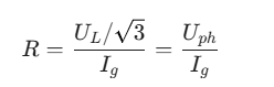
Where UL is the line-to-line voltage (13.8kV) and Ig is the target ground fault current (10A).
Calculation:
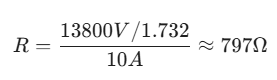
In engineering practice, a standard value of 800Ω is typically selected. Designers must consider the temperature coefficient of the resistor material and ensure the thermal capacity (e.g., 10s or 30s rating) is sufficient to handle the heat dissipation during a fault.
Case Study 1: Application on the 13.8kV Side of a Power Transformer
A factory’s 13.8kV distribution system is supplied by a 10,000kVA, 110kV/13.8kV step-down transformer. To limit the ground fault current to 10A, an NGR is required.
Based on the corrected formula, the required resistance is approximately 800Ω. Considering neutral potential fluctuations and thermal loss, a stainless steel alloy NGR (rather than metal oxide) with a rated voltage of 10kV and a current of 10A is selected. The rated power is calculated as:
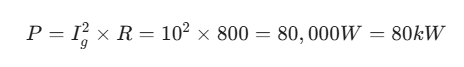
This ensures the resistor can withstand the thermal load during the fault duration. In practice, when a phase-to-ground fault occurs, the NGR limits the current to 10A, enabling the protection relay to isolate the fault within 0.5 seconds, successfully protecting the transformer windings.
Case Study 2: Application on a 13.8kV Synchronous Generator
A captive power plant utilizes a 5,000kW, 13.8kV synchronous generator. Since generator windings are highly sensitive to ground faults, the current must be strictly limited to 10A.
Using the same calculation, an 800Ω resistor is selected. To handle potential voltage surges during generator startup/shutdown, a composite NGR unit with high-grade, corrosion-resistant alloy elements is used, rated at 12kV and 10A with an 80kW thermal capacity. If a ground fault occurs at the generator terminals, the NGR immediately restricts the current to 10A, preventing electromagnetic impact and thermal damage to the stator core. The monitoring system triggers an alarm, allowing the unit to ramp down safely, thus protecting the asset while minimizing generation loss.
Advanced Auxiliary Functions
Beyond current limitation, modern NGR cubicles feature integrated auxiliary functions:
1.Online Monitoring: Utilizes current/voltage transformers and smart modules to track real-time parameters and detect aging or poor contact.
2.Over-temperature Protection: Automatically triggers an alarm or trips the circuit if the resistor exceeds its rated temperature during prolonged faults.
3.Surge Protection: Integrated surge arresters suppress lightning overvoltages entering through the neutral, reinforcing insulation protection.
4.Modular Design: Allows for quick replacement of resistor elements to minimize maintenance downtime.
Conclusion
For a 13.8kV system, the calculation of a 10A NGR must center on the phase voltage and target current, applying the direct formula R = Uph / Ig to arrive at approximately 800Ω. By selecting appropriate materials and integrating smart monitoring, the NGR serves as an indispensable safety barrier, limiting fault damage while enhancing the reliability and maintainability of medium-voltage power systems.
CATEGORIES
- Neutral Grounding Resistor for Transformer
- Generator Neutral Grounding Resistor
- Low Voltage Neutral Grounding Resistor
- Neutral Grounding Arc Suppression Coils (Peterson Coil)
- Neutral Point Gap Grounding Protection Device
- Nitrogen Injection Fire Protection System for Transformer (NIFPS)
- Transformer Air-Cooled Control Equipment
- Nonlinear Neutral Grounding Equipment
LATEST NEWS
- Why Does the Neutral Point of a Large Generator Need to be Reliably Grounded?
- Transformer Neutral Grounding Methods and Applications for High-, Medium-, and Low-Voltage Systems
- How to Accurately Calculate the Neutral Grounding Resistance Value of a Transformer
- Global Top 8 Neutral Grounding Resistor (NGR)Manufacturers
- Neutral Grounding Resistor (NGR) Sizing – Step-by-Step Practical Guide
CONTACT US
WhatsApp: +86-18631228466
Tel: +86-312-5959618
Email: info@orionresistors.com
Add: No. 79, Fuchang Road, Zhongguancun Entrepreneurship Base, Baoding City,China