How to Choose the Right Size of a Neutral Grounding Resistor(NGR) ?
Writer: admin Time:2026-08-21 06:33:23 Browse:144℃
Neutral‑grounding resistor cabinets are deployed in neutral‑resistor‑grounded power systems to limit single‑phase earth‑fault current, suppress over‑voltages, and protect transformers and grid equipment. Cabinet dimensions cannot be arbitrarily minimized, as they are constrained by heat dissipation, resistor body geometry, insulation clearances, thermal‑mechanical short‑circuit withstand capability, and maintenance requirements.
In terms of heat generation and dissipation principles, the core component inside the cabinet is the high‑power neutral‑grounding resistor. During a single‑phase earth fault, the resistor withstands high fault current for a short duration and generates substantial Joule heat. Fault events typically last several seconds with concentrated heat release. An undersized cabinet creates confined inner space, weakening air convection and preventing timely heat dissipation. This causes sharp temperature rise of the resistor body, accelerates resistor material ageing, degrades insulating components under heat, and may result in ablation or even fire. National standards specify limits for short‑term permissible temperature rise of resistors. Confined cabinets lack thermal‑buffer space and directly degrade the equipment’s fault‑withstand capacity.
Insulation and electrical safety clearances represent another critical factor. The cabinet houses neutral‑point transformers, resistor assemblies, busbars and connection terminals subjected to system phase‑to‑earth voltage during operation. Per high‑voltage equipment safety standards, minimum air insulation clearances must be maintained between live parts and the earthed metal enclosure, as well as among live conductors. Cabinet downsizing readily compresses electrical clearances and creepage distances. Partial discharge, flashover and internal cabinet short‑circuits may occur under humid and dusty conditions. Especially in damp substations and outdoor applications, undersized cabinets suffer higher risk of internal condensation, further eroding insulation margins.
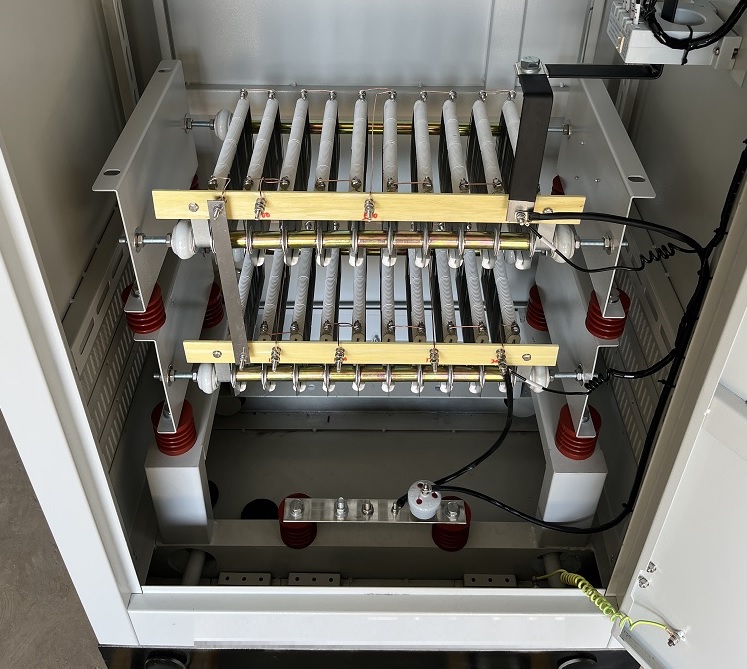
Regarding thermal‑mechanical short‑circuit withstand, fault current flowing through resistors and busbars generates enormous electromagnetic forces. Compact busbar layout with small component spacing in a cramped cabinet makes parts prone to deformation and loosening under short‑circuit electromagnetic stress. A reasonably‑sized cabinet enables rational busbar routing and additional fixing supports to resist short‑circuit impacts, preventing loose connections and displacement or damage of resistor assemblies.
From practical engineering perspectives, reserved space for installation and maintenance is essential. Neutral‑grounding resistors, current transformers, surge arresters and terminals require mounting room. Undersized cabinets lead to congested layout and messy wiring, obstructing later‑stage inspection, component replacement and resistance‑value measurement. Furthermore, certain applications require retrofitting fans or temperature‑humidity controllers, for which compact cabinets provide no spare space.
Nevertheless, neutral‑grounding resistor cabinets should not be oversized unnecessarily. Moderate dimension optimization is acceptable provided heat‑dissipation, insulation and short‑circuit withstand requirements are satisfied. Blind size reduction comes at the cost of fault‑withstand performance, insulation margin and maintainability. The equipment may fail under fault conditions, losing its functions of limiting earth‑fault current and system protection, thereby introducing hidden hazards to power grids. Consequently, during type‑selection and design, cabinet outer dimensions shall be determined by calculating thermal performance and insulation clearances according to fault‑current magnitude and fault duration.

Given conditions: 22 kV system, phase‑voltage 12.7 kV, fault current 10 A, resistance R=1270 Ω, rated fault duration 10 s, indoor installation, altitude ≤1000 m, pollution class II, high‑resistance neutral grounding application.
Short‑time fault power: P=I2R=102×1270=127kW. Massive heat energy is released within 10 s, representing a high‑resistance & low‑fault‑current condition with large thermal capacity.
1. Constraints against undersized cabinet
Insulation clearance constraints. For 22 kV neutral‑point equipment with maximum operating voltage 24 kV, the minimum air clearance between live parts and earthed metal enclosure shall be ≥180 mm. The creepage distance shall be ≥480 mm for pollution class II. Sufficient clearance shall be maintained around resistor stacks, neutral‑point busbars, CTs and surge arresters. Cabinet size reduction will directly squeeze insulation distances and may trigger partial discharge or flashover under condensation and dust contamination.
Thermal dissipation constraints. Steady‑state power loss is negligible, yet enormous heat is generated during the 10‑second fault. The 1270 Ω resistance is realized by series‑connected stainless‑steel grid resistor elements, which occupy physical volume. Free air convection space shall be reserved inside the cabinet; hot air rises upwards and must not be confined by nearby enclosure panels. Although forced‑draft fans are not required for this short‑time duty, internal air volume acts as thermal buffer. Insulator thermal ageing will be accelerated if the inner cavity is too compact.
Component layout & maintenance constraints. Internal devices include neutral‑point disconnector, current transformer, surge arrester and secondary terminal blocks. Bending space for incoming cables and access space for resistance measurement & component replacement shall be reserved. Over‑crowded layout caused by undersizing hinders routine inspection and maintenance.
2. Recommended indoor floor‑standing cabinet dimensions
Width 800 mm × Depth 800 mm × Height 2000 mm (typical industry specification for high‑resistance grounding resistor cabinet).
Width 800 mm: disconnector & CT on left, series resistor stacks in middle, arrester and secondary assemblies on right. Live‑to‑enclosure margin ≥200 mm on both sides.
Depth 800 mm: guarantees clearance between resistors and front/rear panels, provides bending radius for incoming power cables.
Height 2000 mm: vertical installation of resistor elements. Minimum 350 mm plenum space reserved on top for hot‑air accumulation; bottom fitted with natural ventilation louvers.
Dimensions such as W600 × D600 × H1800 or smaller are NOT recommended. Reduced cabinet cuts down insulation margin and internal air volume, leading to excessive temperature rise under fault conditions and crowded wiring, with elevated operational risks.
3. Key engineering notes
This cabinet operates under short‑time duty: 10 A for 10 s, NOT continuous 10‑A loading. Heat is absorbed by internal air volume during fault and dissipated after fault clearance; internal cavity volume is critical rather than resistor element physical size only.
For outdoor cabinet with identical parameters, upgrade to W900 × D900 × H2200 mm for higher insulation margin against condensation, together with reinforced ventilation louvers.
Cabinet shall not be downsized merely for cost saving even if resistor elements are compact. Insulation clearance and thermal‑buffer volume are mandatory design constraints; undersizing will substantially reduce safety margin under fault conditions.

CATEGORIES
- Neutral Grounding Resistor for Transformer
- Generator Neutral Grounding Resistor
- Low Voltage Neutral Grounding Resistor
- Neutral Grounding Arc Suppression Coils (Peterson Coil)
- Neutral Point Gap Grounding Protection Device
- Nitrogen Injection Fire Protection System for Transformer (NIFPS)
- Transformer Air-Cooled Control Equipment
- Nonlinear Neutral Grounding Equipment
LATEST NEWS
- Why Does the Neutral Point of a Large Generator Need to be Reliably Grounded?
- Transformer Neutral Grounding Methods and Applications for High-, Medium-, and Low-Voltage Systems
- How to Accurately Calculate the Neutral Grounding Resistance Value of a Transformer
- Global Top 8 Neutral Grounding Resistor (NGR)Manufacturers
- What Are the Routine and Type Tests for a Transformer Neutral Grounding Resistor (NGR)?
CONTACT US
WhatsApp:
Tel: +86-312-5959618
Email: info@orionresistors.com
Add: No. 79, Fuchang Road, Zhongguancun Entrepreneurship Base, Baoding City,China