The "Must-Read" Monitoring and Alert Checklist for Post-Installed NGR.
Writer: admin Time:2026-05-12 16:09:42 Browse:190℃
I. Precautions for Installation of Neutral Grounding Resistor (NGR) Cabinet
(A) Pre-installation Preparation
Select an appropriate NGR cabinet based on the power system voltage level and capacitive current; verify that the rated parameters match the grounding grid current. Choose a flat site with dry ventilation and no electromagnetic interference; ensure the concrete foundation matches the cabinet specifications and reserve space for operation and heat dissipation. Prepare qualified tools and materials; the grounding wire should preferably be yellow-green double-colored multi-strand copper conductor, and the cross-section of the grounding busbar shall not be less than 1/2 of the main busbar. Inspect the cabinet and internal components upon unboxing to confirm no damage and ensure the protection grade meets IP54 or above.
(B) Installation Process
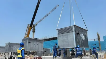
Cabinet Fixation: Place the cabinet horizontally on the preset foundation and secure it firmly with bolts. When using a forklift for handling, align with the angle steel at the bottom shell to avoid damaging the equipment bottom plate. Ensure the cabinet is vertical and non-tilted after installation.
Grounding Connection: Conductive parts such as the metal enclosure of the cabinet and electrical components must be reliably connected to the grounding busbar via dedicated grounding wires; the grounding wires should be short and straight to reduce resistance.
 Note: The grounding terminal of the resistor elements must be reliably connected to the grounding grid through a single-core cable or connection bar (do not connect through the cabinet enclosure). Cable penetrations must be protected and sealed with cable grommets to avoid wire wear. Grounding connection points must have paint and oxide layers removed and be treated for corrosion protection.
Cable Wiring: Wiring must strictly follow the design drawings to distinguish between the inlet and outlet ends to avoid reverse connection. Cable connections must be firm and secured with cable clamps, with wiring terminals clearly marked to ensure reliable secondary circuit wiring. The cross-sectional area of the grounding wire at the S2 terminal of the current transformer (CT) must be consistent with the S1 terminal and not less than 2.5mm2. Multiple sets of CTs must be connected in parallel before connecting to the grounding copper bar.
Insulation and Distance Control: Ensure excellent insulation of all components inside the cabinet during installation. The insulation distance between devices must meet the requirements of the corresponding voltage level. Avoid placing the NGR cabinet too close to other energized equipment to prevent short circuits or discharge accidents.
Safe Operation: Disconnect the system power supply throughout the installation to ensure dead-line operation; operators must wear personal protective equipment (PPE). Live wiring and debugging are strictly prohibited to avoid electric shock accidents.
(C) Installation Completion
Installation of Protective Cover: For outdoor installations, a protective cover must be added to prevent damage from wind, rain, dust, and other environmental factors. Ensure the cabinet's airtightness to avoid insulation degradation caused by condensation.
Comprehensive Inspection: After installation, fully check the cabinet fixation, wiring firmness, and grounding reliability.
Parameter Testing: Use professional instruments for electrical parameter testing, including grounding resistance measurement (error must be ≤10%; typical values are 4-10Ω for high-voltage systems, ≤2Ω for coal mine systems, and ≤1Ω for common grounding bodies) and insulation resistance testing (≥ 500MΩ for 10kV systems).
(D) Specific Installation Precautions for Transformers and Generators
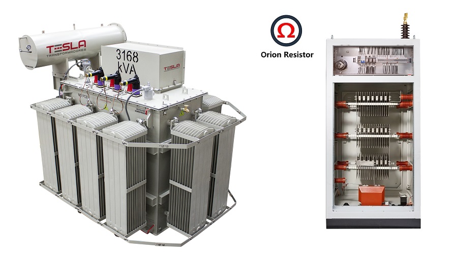
NGR Cabinets for Transformers: Focus on neutral point grounding protection. Ensure the connection path between the neutral bushing and the NGR is as short as possible. The grounding resistance value must match the system zero-sequence current to effectively limit overvoltage during faults. Wiring must be reliably connected to the transformer neutral point and grounding grid to avoid zero-sequence current leakage. If multiple transformers run in parallel, each transformer should typically be equipped with an independent NGR or an interlocking logic must be set; direct paralleling of neutral points without switching is strictly prohibited.
NGR Cabinets for Generators: Focus on protecting the stator windings; the NGR must be directly connected to the generator neutral point. The resistance value must suit the generator capacity, balancing current limiting and arc suppression. The installation position should be as close to the generator outlet end as possible to reduce the impact of capacitance to ground (preferable to arrange the NGR within an indoor area 5-10meters from the generator neutral lead-out, which is the optimal balance between electrical performance and maintenance convenience). It must operate in linkage with the generator protection device. Additionally, the extra heat generated by third harmonic currents must be considered, and a thermal capacity margin should be reserved during selection.
II. Post-installation Precautions for NGR Cabinets
(A) Initial Operation
Closely observe the cabinet status during the energized trial run and put it into formal use only if no abnormalities occur. Re-verify the grounding, insulation parameters, and cabinet temperature within 1-2 weeks. Conduct training for O&M personnel on operation and fault handling.
(B) Daily Operation and Maintenance (O&M)
Perform monthly inspections of the cabinet appearance, wiring, and sealing; increase frequency in humid or dusty environments. Clean the cabinet quarterly and check the anti-corrosion layer; replace severely corroded parts promptly. Control site humidity at ≤75% and cabinet temperature at ≤ 60℃ to ensure good heat dissipation. Periodically measure grounding resistance and insulation resistance; for high-voltage systems, conduct a comprehensive annual test during the main transformer outage; for low-voltage systems, conduct an insulation resistance test (≥ 500MΩ) every six months. Establish a "Grounding Resistance Inspection Record" to detail measured values, seasonal coefficients, and determination results. Pay close attention to the reliability of secondary circuit wiring for current/voltage transformers. If resistance deviation occurs (error >10%) or insulation drops, shut down for maintenance immediately.
(C) Faults and Safety
If abnormalities such as abnormal noise or overheating (> 80℃) occur, stop and troubleshoot immediately; operating with faults is strictly prohibited. Maintenance must strictly follow power outage procedures with PPE worn; unauthorized changes to wiring are strictly prohibited. Calibrate equipment periodically and replace resistor elements and the cabinet when their service life expires. Improve O&M archives and establish emergency plans.
CATEGORIES
- Neutral Grounding Resistor for Transformer
- Generator Neutral Grounding Resistor
- Low Voltage Neutral Grounding Resistor
- Neutral Grounding Arc Suppression Coils (Peterson Coil)
- Neutral Point Gap Grounding Protection Device
- Nitrogen Injection Fire Protection System for Transformer (NIFPS)
- Transformer Air-Cooled Control Equipment
- Nonlinear Neutral Grounding Equipment
LATEST NEWS
- Why Does the Neutral Point of a Large Generator Need to be Reliably Grounded?
- Transformer Neutral Grounding Methods and Applications for High-, Medium-, and Low-Voltage Systems
- How to Accurately Calculate the Neutral Grounding Resistance Value of a Transformer
- Global Top 8 Neutral Grounding Resistor (NGR)Manufacturers
- Neutral Grounding Resistor (NGR) Sizing – Step-by-Step Practical Guide
CONTACT US
WhatsApp: +86-18631228466
Tel: +86-312-5959618
Email: info@orionresistors.com
Add: No. 79, Fuchang Road, Zhongguancun Entrepreneurship Base, Baoding City,China