Design and Selection of Low-Resistance Grounding for 11kV Distribution Networks
Writer: admin Time:2026-05-22 09:09:12 Browse:184℃
I. Substation Overview and the Necessity of Grounding System Retrofit
The substation under consideration employs an 11kV single-bus segmented wiring configuration. Currently, the measured capacitive current on each of the two bus sections is approximately 35A, resulting in a total system capacitive current (IC) of around 70A. With the continuous expansion of urban underground cable networks, the total capacitive current is projected to exceed 50A and eventually reach 100A.
According to international standards for power system overvoltage protection (such as IEEE 142 / Green Book), when the single-phase-to-ground capacitive current in a medium-voltage cable distribution network exceeds 30A, continuing to operate an ungrounded or high-impedance grounded system poses severe operational risks. Intermittent arcing ground faults can easily escalate into catastrophic phase-to-phase or three-phase short circuits due to transient overvoltages. To guarantee grid reliability during single main transformer maintenance (where the remaining transformer must carry the full load) and to accommodate future network expansion, the system neutral point must be retrofitted to a low-resistance grounding (LRG) scheme.
II. Core Considerations in Low-Resistance Grounding System Design
1. Distribution Network Overvoltage Control and Safety Margins
When a single-phase-to-ground fault occurs, the resistive current flowing through the neutral grounding resistor (IR) effectively dissipates the system's trapped capacitive charge. The magnitude of IR is inversely related to the system's internal arcing overvoltage level. Standard power engineering consensus dictates that when IR ≥ 3IC transient overvoltages are optimally suppressed and clamped below 2.5 times the nominal phase-to-neutral voltage. Increasing IR beyond this threshold yields diminishing returns in overvoltage mitigation. Therefore, factoring in the future 100A capacitive current projection, designing the resistor current at IR = 400A perfectly satisfies this criterion while incorporating a robust safety margin (K ) of 1.0 to 1.5.
2. Relay Protection Sensitivity and Grounding Resistance Calculation
Single-phase-to-ground faults are the most frequent fault type in 11kV distribution networks. The total fault current ($I$) at the fault point is the orthogonal vector sum of the resistive and capacitive components, calculated as:
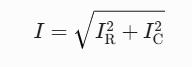
In field practices, due to high-impedance transition faults (e.g., tree branches contacting overhead lines or cables touching high-resistivity concrete surfaces), the actual fault current is often lower than the theoretical dead-short value. Based on global utility experiences in densely populated urban distribution grids, selecting a neutral grounding resistor of approximately 15Ω (corresponding to a nominal fault current of 400A) ensures that zero-sequence overcurrent relays retain high sensitivity. This guarantees accurate fault detection, selective coordination, and reliable tripping even under high-resistance fault conditions.
3. Rapid Fault Isolation and Thermal Constraints
In accordance with international medium-voltage distribution codes, when a ground fault occurs in a heavily cabled network where the fault current exceeds 100A, the protection system must immediately isolate the faulted feeder. Unlike ungrounded networks that permit "clearing faults while remaining energized for several hours," an LRG system utilizes the 400A fault current to trigger clearing within 0.5 seconds. This rapid isolation prevents thermal runaway, completely eliminating the risk of cable insulation breakdown or catastrophic explosive failures.
4. Personnel Safety and Ground Potential Rise (GPR) Control
Injecting a substantial ground fault current into a substation's grounding grid inevitably causes a Ground Potential Rise (GPR), which poses step and touch voltage hazards. In compliance with IEEE 80 (Guide for Safety in AC Substation Grounding), as long as a well-engineered substation grounding grid is paired with high-speed clearing mechanisms (typically limiting the fault duration to less than 0.5 seconds), a fault current of 400A (and even up to 1000A) can be safely dissipated without posing lethal risks to personnel.
5. Electromagnetic Interference (EMI) Mitigation with Communication Systems
High zero-sequence currents can induce hazardous voltages in adjacent parallel telecommunication lines through electromagnetic coupling. International telecommunication safety standards (such as ITU-T directives) specify permissible induced voltage limits—typically 430V for standard copper lines and 630V for high-reliability lines. Global engineering metrics demonstrate that a 400A nominal fault current maintains induced voltages well below these safety limits, ensuring zero electromagnetic interference with modern fiber-optic and well-shielded telecommunication infrastructure.
6. Risk Mitigation in Low-Voltage Distribution Zones
To prevent the high GPR generated during an 11kV ground fault from back-feeding into the low-voltage consumer side (e.g., 230V/400V systems), which could cause user equipment insulation breakdown or severe electric shocks, strict physical isolation is mandatory. Following IEC 60364 and standard industrial wiring guidelines, the high-voltage substation protective grounding grid (Global Grounding System) and the low-voltage distribution system neutral grounding (e.g., a separate TT or TN-S system earthing) must be kept strictly independent and physically separated.
III. Conclusion
In summary, the technical proposal to adopt a neutral low-resistance grounding scheme (with a nominal current of 400A and a resistance value of approximately 15Ω) for this 11kV substation is entirely sound and fully compliant with international power utility codes. This configuration strikes an optimal engineering balance among transient overvoltage suppression, relay sensitivity, personnel safety, and telecommunication interference mitigation. Implementing this approach represents an essential milestone for the safety and maturity of expanding urban power grids.
CATEGORIES
- Neutral Grounding Resistor for Transformer
- Generator Neutral Grounding Resistor
- Low Voltage Neutral Grounding Resistor
- Neutral Grounding Arc Suppression Coils (Peterson Coil)
- Neutral Point Gap Grounding Protection Device
- Nitrogen Injection Fire Protection System for Transformer (NIFPS)
- Transformer Air-Cooled Control Equipment
- Nonlinear Neutral Grounding Equipment
LATEST NEWS
- Why Does the Neutral Point of a Large Generator Need to be Reliably Grounded?
- Transformer Neutral Grounding Methods and Applications for High-, Medium-, and Low-Voltage Systems
- How to Accurately Calculate the Neutral Grounding Resistance Value of a Transformer
- Global Top 8 Neutral Grounding Resistor (NGR)Manufacturers
- How to Accurately Select the Insulation Level of a Neutral Grounding Resistor?
CONTACT US
WhatsApp:
Tel: +86-312-5959618
Email: info@orionresistors.com
Add: No. 79, Fuchang Road, Zhongguancun Entrepreneurship Base, Baoding City,China