6 Neutral Grounding Methods Simplified in One Picture
Writer: admin Time:2026-03-10 14:32:04 Browse:192℃
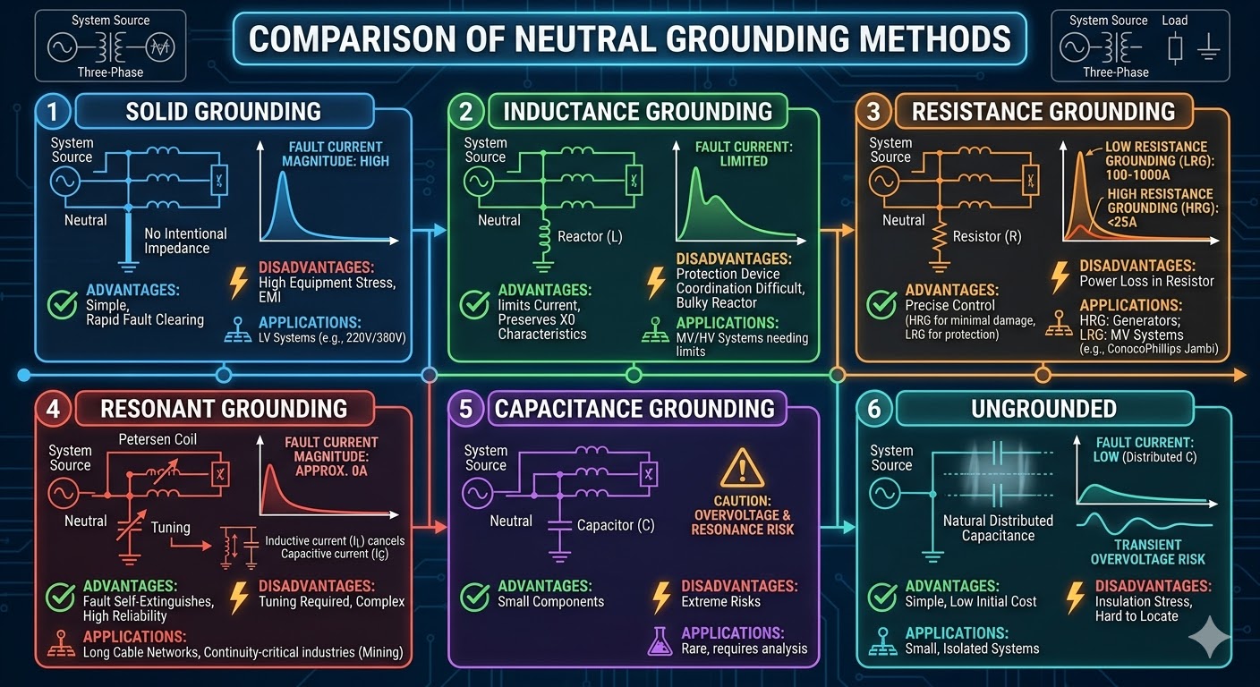
1. Solid Grounding
The neutral point is connected directly to the earth without any intentional intervening impedance. Under this configuration, the magnitude of the ground fault current is extremely high. This method is extensively utilized in Low Voltage (LV) systems.
a. Advantages: Simple design and cost-effective; the high fault current ensures rapid and sensitive operation of protective devices to isolate the faulted circuit; low system overvoltage levels reduce insulation requirements and equipment costs.
b. Disadvantages: Massive single-phase-to-ground fault currents can cause severe mechanical and thermal stress on cables and transformers; high fault currents generate significant Electromagnetic Interference (EMI), affecting nearby communication lines.
c. Applications: Primarily used in LV systems (e.g., 220V/380V residential and industrial distribution); also applied in certain high-capacity high-voltage transmission grids where rapid fault clearing is essential for system stability.
2. Inductance Grounding (Reactor Grounding)
The neutral point is connected to earth via an inductor (reactor). Depending on the inductance value, it is categorized into Low-Inductance and High-Inductance grounding. This method limits the fault current while ensuring the zero-sequence reactance (X0) remains inductive (positive).
a. Advantages: Effectively limits fault current magnitude, reducing physical impact on equipment; maintains inductive zero-sequence reactance to stabilize electrical characteristics and avoid fluctuations caused by abnormal zero-sequence parameters; offers flexibility by choosing between low or high inductance.
b. Disadvantages: Although limited, the fault current remains relatively high, complicating the coordination of protection devices; reactors are bulky, have higher operational losses, and require more space and maintenance.
c. Applications: Medium and high voltage systems where fault current limitation is required but full arc suppression is not the primary goal; industrial power systems with strict requirements for zero-sequence characteristics.
3. Resistance Grounding
The neutral point is connected to earth through a resistor. It is classified into Low-Resistance Grounding (LRG) (typically 100A–1000A fault current) and High-Resistance Grounding (HRG) (fault current <25A, usually 5A–10A).
a. Advantages: Provides precise control over fault currents; HRG minimizes fault damage and prevents fault escalation; LRG provides sufficient current for reliable relay protection; maintains lower overvoltage levels, enhancing insulation safety.
b. Disadvantages: Resistors dissipate energy as heat, increasing energy loss; HRG’s low fault current may result in insensitive protection response, requiring sophisticated monitoring; resistors require periodic maintenance to prevent aging or failure.
c.Applications: * HRG: Commonly used in generator systems and LV systems for specific industrial projects (e.g., ConocoPhillips Jambi, Kaltim 1, and Kaltim 2).
LRG: Widely applied in Medium Voltage (MV) industrial distribution and plant-wide networks.
4. Resonant Grounding (Arc Suppression Coil)
This method utilizes a Petersen Coil (Arc Suppression Coil) at the neutral point. By tuning the inductor's parameters, the inductive current compensates for the system’s capacitive charging current during a ground fault. The objective is to bring the net ground fault current as close to 0 A as possible.
a. Advantages: Maximizes fault current neutralization, allowing ground fault arcs to self-extinguish; minimizes stress on equipment; allows the system to continue operating during a single-phase fault, significantly improving power reliability.
b. Disadvantages: Resonance conditions are easily disrupted by changes in system parameters (e.g., changes in cable length/capacitance), requiring frequent re-tuning; complex and expensive equipment; difficult fault localization requires specialized monitoring systems.
c. Applications: Systems with high terrestrial capacitance (e.g., long cable networks); industrial sectors requiring high continuity of service like mining and chemical plants.
5. Capacitance Grounding
The neutral point is connected to earth via a capacitor. This method is rarely employed and must undergo rigorous analytical assessment due to the high risk of transient overvoltages and ferroresonance.
a. Advantages: Compact and lightweight components; extremely low operational power loss; can theoretically assist in reactive power compensation.
b. Disadvantages: High susceptibility to severe overvoltages and resonance that can destroy equipment; extremely narrow application range; ineffective at limiting fault currents, making protection difficult.
c. Applications: Extremely niche; only used in specialized systems after exhaustive simulation and risk assessment.
6. Ungrounded (Isolated Neutral)
The neutral point has no intentional connection to earth. Although physically disconnected, the system is inherently coupled to earth via the distributed capacitance of cables, transformer windings, and generator windings.
a. Advantages: Simplest architecture with no additional grounding equipment and lowest initial investment; low fault currents (limited to capacitive charging current) allow for short-term continued operation while tracing the fault.
b. Disadvantages: High risk of arcing ground overvoltages (transient overvoltages) which can lead to insulation breakdown; difficult to locate faults quickly; potential for resonance overvoltage if system capacitance changes.
c. Applications: Small-capacity, short-distance LV or MV systems; scenarios where continuity is prioritized over insulation stress (usage is declining in modern engineering).
CATEGORIES
- Neutral Grounding Resistor for Transformer
- Generator Neutral Grounding Resistor
- Low Voltage Neutral Grounding Resistor
- Neutral Grounding Arc Suppression Coils (Peterson Coil)
- Neutral Point Gap Grounding Protection Device
- Nitrogen Injection Fire Protection System for Transformer (NIFPS)
- Transformer Air-Cooled Control Equipment
- Nonlinear Neutral Grounding Equipment
LATEST NEWS
- Why Does the Neutral Point of a Large Generator Need to be Reliably Grounded?
- Transformer Neutral Grounding Methods and Applications for High-, Medium-, and Low-Voltage Systems
- How to Accurately Calculate the Neutral Grounding Resistance Value of a Transformer
- Global Top 8 Neutral Grounding Resistor (NGR)Manufacturers
- Neutral Grounding Resistor (NGR) Sizing – Step-by-Step Practical Guide
CONTACT US
WhatsApp: +86-18631228466
Tel: +86-312-5959618
Email: info@orionresistors.com
Add: No. 79, Fuchang Road, Zhongguancun Entrepreneurship Base, Baoding City,China