What Are the Voltage and Current, and Phase Changes when a Ground Fault Occurs in an Ungrounded System?
Writer: admin Time:2025-09-15 18:05:59 Browse:577℃
Ungrounded neutral systems, also known as isolated neutral systems, are widely used in medium-voltage power networks.
However, they present certain drawbacks, which can be better understood by analyzing voltage and current behaviors
during a single-phase-to-ground fault.
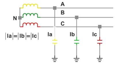
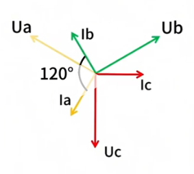
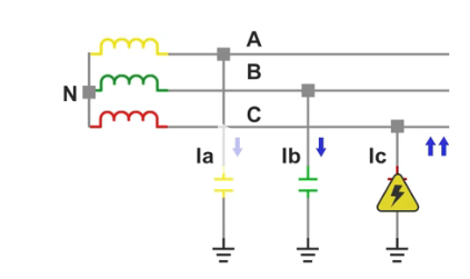
In normal operation, each phase conductor (cable or overhead line) has an equivalent capacitance to ground. Since the system
is three-phase and symmetrical, the capacitances of the three phases are approximately equal, and so are the corresponding
capacitive currents (Ia, Ib, Ic), which lead their respective phase voltages by 90° and are separated from each other by 120°.
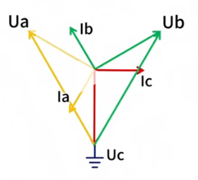
When a single-phase-to-ground fault occurs (for example, on phase C), the ground capacitance of the faulted phase is
short-circuited,making the phase-to-ground voltage of phase C drop to zero. Because the neutral point is isolated, it shifts,
causing the phase-to-ground voltages of the healthy phases A and B to rise to √3 times their normal value. Consequently,
the capacitive currents of phases A and B also increase by a factor of √3. At this stage, the phase angle between the capacitive
currents of A and B becomes 60°.
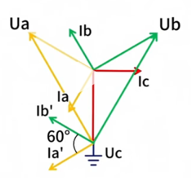
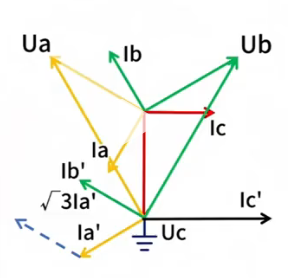
From a current flow perspective, the capacitive current from phase A flows through its phase-to-ground capacitance, the earth,
and the ground fault point of phase C, then returns via phase C to the winding. A similar path applies for phase B. As a result,
the ground fault point carries the resultant current of phases A and B. By vector summation, since their phase angle difference
is 60°, the ground fault current is calculated as 3Ia, i.e., three times the single-phase capacitive current, and its direction is opposite
to the currents of phases A and B.
Calculation of current: 2xcos30°x√3la=2x√3/2x√3la=3la
According to the standard IEEE Std. 142-2007, the capacitive current at the ground fault point in ungrounded systems
should not exceed 10 A. This implies that the single-phase capacitive current should be limited to about 3.3 A. If the fault
current exceeds 10 A, the consequences may be severe, including equipment damage, overvoltage stresses, and difficulties
in fault detection. Therefore, careful system design and parameter control are essential to ensure safe and reliable operation
of ungrounded neutral systems.
Related Articles:
How to Accurately Calculate the Neutral Grounding Resistance Value of a Transformer
Global Top 8 Neutral Grounding Resistor (NGR)Manufacturers
Transformer Neutral Grounding Methods and Applications for High-, Medium-, and Low-Voltage Systems
Solid, Resistance, and Ungrounded Systems — Which Is Safer for your Network?
Why Does the Neutral Point of a Large Generator Need to be Reliably Grounded?


CATEGORIES
- Neutral Grounding Resistor for Transformer
- Generator Neutral Grounding Resistor
- Low Voltage Neutral Grounding Resistor
- Neutral Grounding Arc Suppression Coils (Peterson Coil)
- Neutral Point Gap Grounding Protection Device
- Nitrogen Injection Fire Protection System for Transformer (NIFPS)
- Transformer Air-Cooled Control Equipment
- Nonlinear Neutral Grounding Equipment
LATEST NEWS
- Why Does the Neutral Point of a Large Generator Need to be Reliably Grounded?
- Transformer Neutral Grounding Methods and Applications for High-, Medium-, and Low-Voltage Systems
- How to Accurately Calculate the Neutral Grounding Resistance Value of a Transformer
- Global Top 8 Neutral Grounding Resistor (NGR)Manufacturers
- Neutral Grounding Resistor (NGR) Sizing – Step-by-Step Practical Guide
CONTACT US
WhatsApp: +86-18631228466
Tel: +86-312-5959618
Email: info@orionresistors.com
Add: No. 79, Fuchang Road, Zhongguancun Entrepreneurship Base, Baoding City,China