9 Most Common Grounding Applications and Recommended Resistance Values
Writer: admin Time:2025-10-17 15:02:38 Browse:1214℃
Grounding plays a vital role in ensuring the safety and reliability of electrical systems. Different grounding methods—such as solid grounding, resistance grounding, and reactance grounding—are applied according to voltage levels and system requirements. This guide provides the most comprehensive overview of grounding resistor configurations and their recommended resistance values. Whether for power generation, transmission, or industrial systems, understanding how to select the proper grounding type and resistance is essential to limiting fault currents, protecting equipment, and maintaining stable system operation.
1. Operational Grounding (Working Ground)
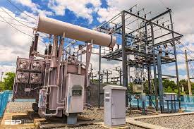
Recommended Resistance: ≤ 4 Ω (for low-voltage systems; ≤ 0.5 Ω for substations)
Operational grounding provides a stable reference voltage for the neutral conductor in an electrical system, preventing voltage imbalances caused by potential shifts in the neutral conductor. In low-voltage systems, the resistance should be ≤4Ω, while in substations, where larger power scales and more stringent voltage stability are required, the resistance must be ≤0.5Ω. A high resistance may cause fluctuations in neutral potential due to load changes, possibly leading to unbalanced three-phase voltages and damaging sensitive equipment. On the other hand, too low a resistance may result in excessive fault current during short circuits, potentially damaging system components. A resistance of 4Ω is a balanced value, ensuring both voltage stability and fault current control, and is widely used in residential and industrial low-voltage power supply systems.
2. Protective Grounding (Safety Ground)
Recommended Resistance: ≤ 4 Ω
Protective grounding is designed for the conductive enclosures of electrical equipment (e.g., motor housings, distribution panel bodies) to prevent electric shock hazards when insulation failure occurs. The resistance must be ≤4Ω to ensure that sufficient fault current flows in the event of leakage, triggering protection devices such as circuit breakers or fuses to disconnect the power supply. If the resistance is too high, the fault current will be too small for protection devices to act in time, leaving the enclosure live and posing a shock risk to personnel. This is commonly used for household appliances, industrial machinery, and electrical cabinets.
3. Repeated Grounding
Recommended Resistance: ≤ 10 Ω
Repeated grounding involves setting up additional grounding points along the neutral conductor of the distribution system (e.g., at branch points or terminals), supplementing the main grounding system. The required resistance is ≤10Ω, slightly higher than that for protective grounding, as it serves as a backup and reinforcement. In the event of a fault in the main grounding system, repeated grounding can temporarily take over the grounding function, preventing the expansion of the live enclosure after a neutral conductor disconnects. It also reduces neutral line impedance, minimizing voltage drop and improving the reliability of the distribution system. This is commonly used in long-distance distribution scenarios such as overhead lines and cable distribution systems.
4. Lightning Protection Grounding
Recommended Resistance: ≤ 10 Ω (≤ 5 Ω for critical facilities)
Lightning protection grounding aims to create a low-impedance pathway to safely direct the massive current from a lightning strike into the earth, preventing lightning-induced overvoltages that could damage equipment or cause fires and electric shocks. In typical scenarios, the resistance should be ≤10Ω, while in critical facilities such as substations, communication stations, and data centers, where the lightning risk is high and equipment is valuable, the resistance must be ≤5Ω. A lower resistance ensures rapid dissipation of lightning current, reduces voltage drop across the grounding system, and lowers the risk of dielectric breakdown of equipment insulation. It is often used in conjunction with lightning rods, bands, and other protection devices for buildings, power transmission lines, and communication towers.
5. Static Electricity Grounding
Recommended Resistance: ≤ 100 Ω
Static electricity grounding is used to eliminate static charge accumulation caused by friction or induction during production, storage, or transportation, preventing sparks that could ignite flammable materials or damage electronic components. The resistance should be ≤100Ω since the discharge current from static electricity is typically small, and the focus is on maintaining grounding continuity. Interruptions in grounding could prevent the release of static charge. This type of grounding is commonly used in petroleum and chemical storage tanks, fuel pipelines, and electronic chip production workshops to safely dissipate static charges and ensure production safety and product quality.
6. Combined Protective and Lightning Grounding
Recommended Resistance: ≤ 1 Ω
This grounding system serves both protective and lightning protection functions, with a stringent resistance requirement of ≤1Ω. In high-demand areas such as substations, communication centers, and control buildings, where equipment density and safety requirements are high, setting up separate protective and lightning grounding systems would increase system complexity and cost. A combined system allows for shared grounding networks, meeting both needs efficiently. A low resistance of 1Ω ensures rapid dissipation of lightning current during strikes while triggering protection devices during electrical faults, preventing safety hazards due to conflicts between grounding functions. It is an effective grounding solution for high-security environments.
7. Electronic Information Equipment or Data Center Grounding
Recommended Resistance: ≤ 1 Ω (ideal ≤ 0.5 Ω)
This type of grounding is specifically designed to ensure signal stability and electromagnetic interference (EMI) suppression for electronic equipment. The resistance requirement is ≤1Ω, ideally ≤0.5Ω. Electronic equipment such as servers, switches, and precision instruments are extremely sensitive to fluctuations in signal reference potential. High grounding resistance can cause voltage instability and signal distortion. A low resistance ensures effective suppression of EMI, reducing the impact of external electromagnetic fields on equipment signals and improving system reliability. In data centers, where numerous servers run in a complex electromagnetic environment, a low-resistance grounding system ensures synchronized signal operation, prevents data transmission errors, and guarantees continuous system operation.
8. Transformer Neutral Grounding (≤ 1000 V Systems)
Recommended Resistance: ≤ 10 Ω (subject to system design)
The main purpose of transformer neutral point grounding is to generate a sufficient fault current in the event of a single-phase grounding fault, enabling protection relays (e.g., overcurrent relays) to act correctly and prevent excessive fault current from overheating and damaging the transformer. The required resistance is ≤10Ω, but the actual value should be adjusted based on the system design: if the system voltage is higher or the cable capacitance is large, a lower resistance may be necessary to ensure adequate fault current; if the protection relay sensitivity is high, the resistance can be fine-tuned to trigger the relay at the correct fault current. In low-voltage distribution transformers, proper neutral point grounding ensures fast power disconnection during faults, protecting transformer windings while maintaining system stability by preventing excessive neutral line current during normal operation. It is a crucial grounding element in low-voltage power supply systems.

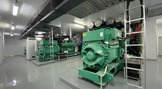
9. Generator Neutral Grounding.
Generator neutral point grounding must balance fault protection, equipment insulation safety, and system stability. It is primarily divided into three methods: direct grounding, resistance grounding, and arc suppression coil grounding, each with distinct resistance requirements and applicable scenarios.
Direct Grounding: This method is only suitable for generators below 10kV and with smaller capacities (usually ≤10MW). There are no additional resistance requirements, but during faults, it generates a large short-circuit current that can easily damage the generator stator windings. It is typically used in scenarios with minimal power continuity requirements.
Resistance Grounding: This is the most common method for medium to large-capacity generators (10-100MW). The grounding resistance needs to be adjusted based on the generator's capacity, typically aiming to limit fault current to 500-1000A (low-voltage generators) or 100-300A (high-voltage generators). For example, a 10MW low-voltage generator usually has a 5-10Ω grounding resistor. This setup avoids excessive fault current that could impact the windings, triggers protection devices quickly, and suppresses transient overvoltages that could damage insulation. It is widely used in industrial backup power stations and small to medium-sized power plants.
Arc Suppression Coil Grounding: This method is suitable for high-voltage, large-capacity generators (≥100MW, voltage 10kV and above) and systems with large capacitive current during single-phase grounding (usually >5A). There is no strict resistance value requirement. The core of this method is to use the inductive current from the arc suppression coil to cancel out the system's capacitive current, allowing the grounding arc to extinguish on its own and preventing fault expansion. This method is commonly used in large thermal power and hydropower units, effectively reducing the repetitive impact of single-phase ground faults on the generator insulation, ensuring long-term stable operation of the units, and reducing power outages, thus improving power supply reliability.
Notes
Ground Resistance: The lower, the better — ensures better conductivity and safer fault dissipation.
Insulation Resistance: The higher, the better — ensures insulation integrity and safety.
Selecting the right grounding resistor value is not only a technical decision but also a key factor in achieving system reliability and safety. By understanding grounding types and their resistance recommendations, engineers can design systems that minimize damage, simplify maintenance, and enhance fault response. This guide aims to provide practical reference data for optimizing electrical protection and achieving long-term stability.
Related Articles:
How to Accurately Calculate the Neutral Grounding Resistance Value of a Transformer
Global Top 8 Neutral Grounding Resistor (NGR)Manufacturers
Transformer Neutral Grounding Methods and Applications for High-, Medium-, and Low-Voltage Systems
Solid, Resistance, and Ungrounded Systems — Which Is Safer for your Network?
Why Does the Neutral Point of a Large Generator Need to be Reliably Grounded?


CATEGORIES
- Neutral Grounding Resistor for Transformer
- Generator Neutral Grounding Resistor
- Low Voltage Neutral Grounding Resistor
- Neutral Grounding Arc Suppression Coils (Peterson Coil)
- Neutral Point Gap Grounding Protection Device
- Nitrogen Injection Fire Protection System for Transformer (NIFPS)
- Transformer Air-Cooled Control Equipment
- Nonlinear Neutral Grounding Equipment
LATEST NEWS
- Why Does the Neutral Point of a Large Generator Need to be Reliably Grounded?
- Transformer Neutral Grounding Methods and Applications for High-, Medium-, and Low-Voltage Systems
- How to Accurately Calculate the Neutral Grounding Resistance Value of a Transformer
- Global Top 8 Neutral Grounding Resistor (NGR)Manufacturers
- Neutral Grounding Resistor (NGR) Sizing – Step-by-Step Practical Guide
CONTACT US
WhatsApp: +86-18631228466
Tel: +86-312-5959618
Email: info@orionresistors.com
Add: No. 79, Fuchang Road, Zhongguancun Entrepreneurship Base, Baoding City,China