Why Neutral Grounding Resistors (NGR) Are the Standard for 10–15 kV Urban Power Grids
Writer: admin Time:2026-03-30 16:28:56 Browse:82℃
1. The Growing Necessity for NGR in Modern Distribution
Historically, 10–15 kV networks used "isolated neutral" systems. This worked when overhead lines had low capacitive currents (<10 A). However, the shift to extensive underground cabling has increased capacitance to levels where the air or insulation can no longer self-extinguish a ground fault.
Without a Neutral Grounding Resistor (NGR), these high capacitive currents lead to "arcing ground faults." This phenomenon creates transient overvoltages (3.5–5x nominal voltage) that can bypass surge arresters and cause catastrophic insulation failure across the entire 10–15 kV busbar. Integrating an NGR is the industry-standard solution to dissipate this energy and stabilize the system.
2. How the NGR System Works
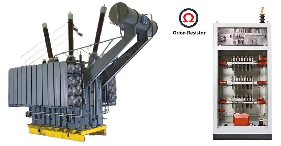
In a typical 11 kV or 15 kV delta-connected system, there is no natural neutral point to ground. To incorporate an NGR, engineers use a Grounding Transformer (typically Zig-zag or Star-Delta) to create an artificial neutral.
The Neutral Grounding Resistor (NGR) is then connected between this artificial neutral and the station earth grid.
The "Swamping" Principle: The NGR is sized to provide a resistive fault current ( IR ) that is equal to or greater than the system's total capacitive charging current ( Ic ).
Current Limitation: By selecting a specific resistance value (often around 10–20 Ω), the NGR limits the single-phase-to-ground fault current to a controlled range (typically 400 A, 600 A, or 1000 A). This is sufficient to trigger protection relays without causing the massive mechanical and thermal stress associated with solid grounding.
3. Critical Advantages of NGR Integration
A. Rapid Fault Detection via NGR Monitoring
In ungrounded systems, identifying a faulted feeder is like finding a needle in a haystack because the fault current is so small. With an NGR, the fault produces a predictable, measurable current. Zero-sequence CTs (Current Transformers) can then detect this specific current, allowing the relay to trip only the faulted feeder within cycles.
B. Protection of High-Value Assets
The NGR acts as a safety valve. By limiting the fault current, it prevents:
Burning of Iron Cores: It limits damage to the laminated cores of motors and transformers during an internal fault.
Cable Explosion: It prevents high-energy arcs from blowing out cable joints, which reduces repair time and costs.
Switchgear Longevity: It reduces the duty on circuit breakers by ensuring they only have to interrupt controlled resistive currents rather than erratic capacitive arcs.
C. Enhanced Personnel Safety and Step/Touch Voltage Control
The NGR provides a defined path for fault current. When paired with high-speed relaying, it ensures that ground faults are cleared in less than 100ms. This minimizes the duration of Step and Touch Voltages, protecting utility workers and the public in densely populated urban environments.
4. Conclusion: NGR as the Heart of Grid Reliability
As urban 10–15 kV grids become more complex and cable-heavy, the Neutral Grounding Resistor (NGR) has evolved from an optional accessory to a critical infrastructure component. By providing a controlled discharge path for fault energy, NGRs enable precise relay coordination, protect expensive transformer assets, and ensure the safety of modern power distribution.
CATEGORIES
- Neutral Grounding Resistor for Transformer
- Generator Neutral Grounding Resistor
- Low Voltage Neutral Grounding Resistor
- Neutral Grounding Arc Suppression Coils (Peterson Coil)
- Neutral Point Gap Grounding Protection Device
- Nitrogen Injection Fire Protection System for Transformer (NIFPS)
- Transformer Air-Cooled Control Equipment
- Nonlinear Neutral Grounding Equipment
LATEST NEWS
- Why Does the Neutral Point of a Large Generator Need to be Reliably Grounded?
- Transformer Neutral Grounding Methods and Applications for High-, Medium-, and Low-Voltage Systems
- How to Accurately Calculate the Neutral Grounding Resistance Value of a Transformer
- Global Top 8 Neutral Grounding Resistor (NGR)Manufacturers
- The Importance of Neutral Grounding Systems at a Glance
CONTACT US
WhatsApp: +86-18631228466
Tel: +86-312-5959618
Email: info@orionresistors.com
Add: No. 79, Fuchang Road, Zhongguancun Entrepreneurship Base, Baoding City,China