How to Accurately Select the Fault Current Rating of a Transformer Neutral Grounding Resistor (NGR)
Writer: admin Time:2026-11-03 15:01:53 Browse:82℃
1. What Is an NGR and Why Is Its Fault Current Important?
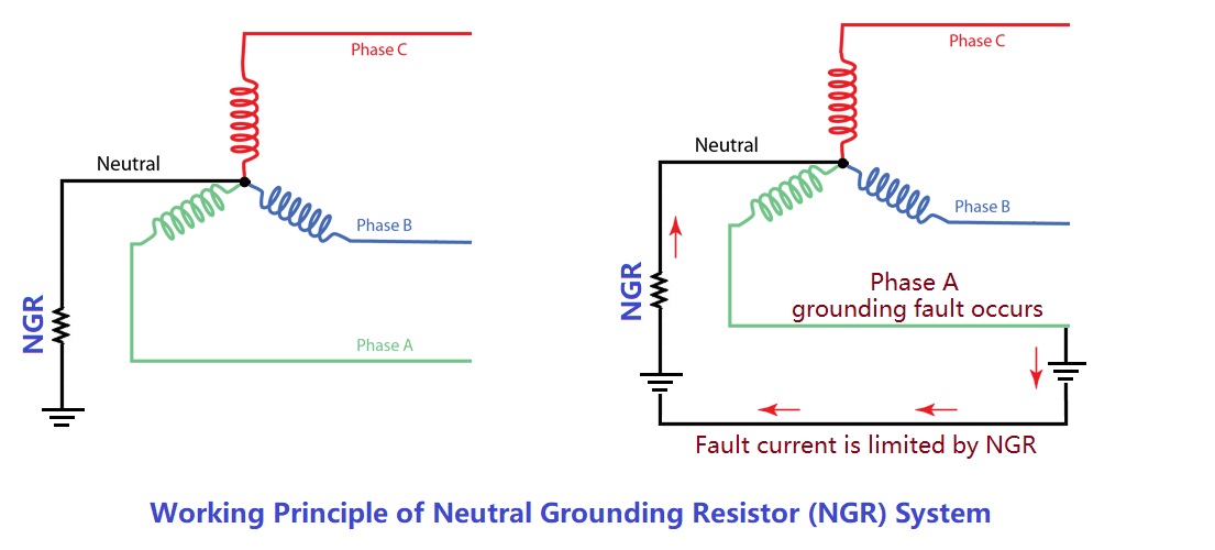
A Neutral Grounding Resistor (NGR), also commonly referred to as a Neutral Earthing Resistor (NER) in IEC-compliant systems, is connected between the neutral point of a power transformer or generator and earth. Its primary function is to limit the magnitude of the fault current flowing during a single-line-to-ground (SLG) fault.Under normal balanced operating conditions, the three-phase system remains symmetrical, and the neutral point potential stays close to true earth potential.
When a phase-to-ground fault occurs, the neutral point experiences a voltage displacement, establishing a controlled current path through the NGR. The resistor restricts the fault current to a pre-engineered value.Without an NGR, an ungrounded or solidly grounded system can experience severe consequences. Solidly grounded systems produce massive fault currents that inflict catastrophic thermal and mechanical damage on transformer windings, cables, busbars, and switchgear. Conversely, ungrounded systems are prone to hazardous intermittent arcing ground overvoltages.
By integrating an NGR, the fault current is precisely bounded, enabling protective relays to reliably detect and isolate the faulted circuit while minimizing stress on electrical assets.
Basic Working Principle
The foundational relationship in NGR sizing is expressed by Ohm's Law:
Ig = VLN / R
Where:
Ig = Ground-fault current (A)
VLN = System line-to-neutral voltage (V)
R = Neutral grounding resistance (Ω)
Rearranging the formula yields the required resistance:
R = VLN / Ig
This indicates that for a given system voltage, a higher target fault current requires a lower resistance, whereas a lower fault current demands a higher resistance.
The selected fault current cannot be chosen arbitrarily; it must be dictated by system grounding philosophy, protective relay coordination, total capacitive charging current, and equipment thermal-mechanical withstand capabilities.
2. Step 1: Determine System Voltage and Neutral Voltage
The initial design step is to establish the system's rated line-to-line voltage (VLL).
For a three-phase star (wye) connected transformer, the voltage applied across the NGR during a single-line-to-ground fault is the line-to-neutral voltage (VLN), rather than the line-to-line voltage.
The conversion relationship is:
VLN = VLL / √3
Typical medium-voltage system voltage relationships are outlined below:
| System Line Voltage (VLL) | Line-to-Neutral Voltage (VLN) |
| 3.3 kV | 1.905 kV |
| 6.6 kV | 3.811 kV |
| 11 kV | 6.351 kV |
| 13.8 kV | 7.967 kV |
| 33 kV | 19.053 kV |
This distinction is critical: for a 13.8 kV system, the NGR voltage rating must be engineered based on 7.97 kV rather than 13.8 kV.
This calculation assumes a direct, accessible star-connected transformer neutral with the NGR connected directly between the neutral and earth. Systems utilizing zig-zag grounding transformers require equivalent zero-sequence circuit analysis.
3. Step 2: Establish the Grounding Philosophy (HRG vs. LRG)
Before finalizing the fault current magnitude, power system engineers must determine whether High Resistance Grounding (HRG) or Low Resistance Grounding (LRG) applies.
High Resistance Grounding (HRG)
HRG is designed to limit the single-line-to-ground fault current to a very low level, typically ranging from a few amperes up to 10 A.
Typical Applications:
1. Continuous process industrial facilities where unplanned outages incur massive economic losses.
2. Systems where the first ground fault initiates an alarm rather than an immediate tripping action.
3. Networks with relatively low total capacitive charging current.
Duty Rating:Because HRG systems are designed to operate safely with a persistent ground fault until maintenance personnel locate and isolate it, the NGR must be rated for Continuous Duty.
Sizing Constraint:To prevent destructive intermittent arcing ground overvoltages, the resistive grounding current must equal or exceed the total system capacitive charging current:
IR ≥ IC
Where:
IR = Resistor-derived grounding current (A)
IC = Total system capacitive charging current (A)
Low Resistance Grounding (LRG)
LRG allows a higher, controlled fault current, commonly spanning from 100 A to 1000 A.
Typical Applications:
1. Medium-voltage industrial distribution networks.
2. Large transformer auxiliary power systems.
3. Mining and heavy manufacturing installations.
4. Networks where ground faults must be cleared rapidly by protective relays.
Duty Rating:Since LRG systems rely on immediate protective relay operation to trip the circuit within hundreds of milliseconds, the NGR is typically specified as Short-time Duty (e.g., 10 seconds, 30 seconds, or 60 seconds), significantly optimizing enclosure footprint and capital cost.
4. Step 3: Determine the Required Ground-Fault Current
Sizing the fault current is the most critical engineering task in NGR specification, requiring the evaluation of four primary factors:
Factor 1: Protection Relay Sensitivity and Selectivity
The NGR current must be high enough for zero-sequence overcurrent relays and current transformers (CTs) to detect the fault reliably under all operating states, while accounting for relay pickup tolerances and possible fault transition resistance (Rf). Insensitive settings cause relay failure to trip, while overly sensitive settings lead to nuisance tripping.
Factor 2: System Capacitive Charging Current (IC)
Every cable network, transformer winding, and rotating machine exhibits distributed capacitance to earth. As electrical networks expand, total charging current increases. In HRG designs, the NGR current must continuously override this capacitive charging current (IR ≥IC) with adequate design margin.
Factor 3: Equipment Withstand Capability
A higher fault current improves relay discrimination but escalates thermal and mechanical stress across system components. Engineers must verify the short-circuit thermal and dynamic withstand limits of:
1. Transformer neutral bushings and internal windings
2. Grounding transformers (if applicable)
3. Power cables and shielding
4. Switchgear busbars and earthing conductors
Factor 4: Fault Duration
The current rating must be coupled with a strict time rating (e.g., 10 s, 30 s, 60 s, or continuous). This duration reflects primary relay clearing times plus backup protection coordination margins, ensuring the resistor element temperature remains within allowable metallurgical limits.
5. Step 4: Calculate NGR Resistance and Thermal Energy
Once the fault current and system voltage are established, the required resistance is calculated as follows:
R = VLN / Ig = VLL / (√3 × Ig)
Example 1: NGR Sizing for a 3.3 kV System
Design Parameters:
1. System Line Voltage (VLL): 3.3 kV (3300 V)
2. Grounding Type: Low Resistance Grounding (LRG)
3. Target Fault Current (Ig): 100 A
4. Fault Duration: 10 seconds
Calculation Steps:
Line-to-Neutral Voltage:VLN = 3300 / √3 = 1905.3 V
Resistance Value:R = 1905.3 / 100 = 19.05 Ω
Thermal Energy Dissipation:Instantaneous Power (P) = Ig2 × R = 1002 × 19.05 = 190.5 kW
Total Energy (10 s) (E) = P × t = 190.5 kW × 10 s = 1905 kJ (1.905 MJ)
(Note: This specifies a thermal capacity to absorb 1905 kJ without exceeding temperature limits, rather than a continuous 190.5 kW power rating.)
Resistance Options for 3.3 kV LRG Systems:
| Target Current (Ig) | Calculated Resistance (R) |
| 50 A | 38.11 Ω |
| 100 A | 19.05 Ω |
| 200 A | 9.53 Ω |
| 400 A | 4.76 Ω |
Example 2: NGR Sizing for a 13.8 kV System
Design Parameters:
1. System Line Voltage (VLL): 13.8 kV (13800 V)
2. Grounding Type: Low Resistance Grounding (LRG)
3. Target Fault Current (Ig): 50 A
4. Fault Duration: 10 seconds
Calculation Steps:
Line-to-Neutral Voltage: VLN = 13800 / √3 = 7967.4 V
Resistance Value: R = 7967.4 / 50 = 159.35 Ω
Thermal Energy Dissipation:Instantaneous Power (P) = 502 × 159.35 = 398.4 kW
Total Energy (10s) (E) = 398.4 kW × 10 s = 3984 kJ (3.984 MJ)
Engineering Insight: Although the 13.8 kV system requires half the current (50 A) of the 3.3 kV example (100 A), its instantaneous thermal power dissipation is more than double due to the higher voltage tier.
Resistance Options for 13.8 kV LRG Systems:
| Target Current (Ig) | Calculated Resistance (R) |
| 25 A | 318.70 Ω |
| 50 A | 159.35 Ω |
| 100 A | 79.67 Ω |
| 200 A | 39.84 Ω |
| 400 A | 19.92 Ω |
6. Step 5: Verify Actual Fault Current and Transition Resistance
The simplified formula Ig = VLN / R assumes an ideal bolted metallic fault (Rf = 0). In real-world installations, fault conditions include transition resistance (e.g., arc resistance, structural contact, or grounding path impedance).
The actual fault current equation incorporates transition resistance:
Iactual = VLN / √(R2 + R2f)
When transition resistance is present, the actual fault current decreases. Protective relay settings must be coordinated against the minimum anticipated fault current to guarantee trip reliability. Furthermore, transformer zero-sequence impedance should be factored into high-precision engineering reviews.
7. Practical NGR Specification Checklist
Prior to issuing technical data sheets to manufacturers, engineers must verify the following parameters against IEEE C57.32 standards:
| Technical Parameter | Engineering Verification Requirement |
| System Line Voltage (VLL) | Nominal system operating voltage |
| NGR Rated Voltage (VLN) | Maximum line-to-neutral voltage rating |
| Neutral Configuration | Direct transformer neutral or grounding transformer |
| Grounding Method | High Resistance Grounding (HRG) or Low Resistance Grounding (LRG) |
| Rated Fault Current (Ig) | Specified ampacity limit |
| Resistance Value (R) | Ohmic value at reference temperature (20°C) |
| Duty / Duration | Continuous or short-time rated (10s, 30s, 60s) |
| System Charging Current (IC) | Total network capacitive charging current |
| Protection Coordination | CT ratio, relay pickup, and selectivity criteria |
| Insulation Level | Power-frequency withstand and BIL ratings |
| Enclosure & IP Rating | Environmental protection (e.g., IP23, IP54, stainless steel finish) |
| Design Standards | Compliance with IEEE C57.32 and IEC 60076-16 |
8. Conclusion
Selecting the correct NGR fault current rating requires a rigorous engineering workflow: establishing system voltages, evaluating grounding philosophy, analyzing capacitive charging currents, verifying equipment withstand limits, and calculating precise ohmic and thermal parameters.
By applying standardized calculations—such as obtaining ~19.05 Ω for a 3.3 kV / 100 A system or ~159.35 Ω for a 13.8 kV / 50 A system—and accounting for real-world transition impedances, engineers ensure that the selected NGR limits fault energy effectively while preserving absolute protection reliability.
CATEGORIES
- Neutral Grounding Resistor for Transformer
- Generator Neutral Grounding Resistor
- Low Voltage Neutral Grounding Resistor
- Neutral Grounding Arc Suppression Coils (Peterson Coil)
- Neutral Point Gap Grounding Protection Device
- Nitrogen Injection Fire Protection System for Transformer (NIFPS)
- Transformer Air-Cooled Control Equipment
- Nonlinear Neutral Grounding Equipment
LATEST NEWS
- Why Does the Neutral Point of a Large Generator Need to be Reliably Grounded?
- Transformer Neutral Grounding Methods and Applications for High-, Medium-, and Low-Voltage Systems
- How to Accurately Calculate the Neutral Grounding Resistance Value of a Transformer
- Global Top 8 Neutral Grounding Resistor (NGR)Manufacturers
- How to Select the Correct Neutral Grounding Resistor (NGR) for a Transformer
CONTACT US
WhatsApp:
Tel: +86-312-5959618
Email: info@orionresistors.com
Add: No. 79, Fuchang Road, Zhongguancun Entrepreneurship Base, Baoding City,China