How to Select the Correct Neutral Grounding Resistor (NGR) for a Transformer
Writer: admin Time:2026-11-12 15:04:21 Browse:8℃
Introduction
Selecting the correct neutral grounding resistor (NGR) is essential for protecting power transformers and ensuring the reliable operation of an electrical distribution system. An improperly sized resistor may result in excessive ground fault current, insufficient protection sensitivity, or unacceptable transient overvoltages.
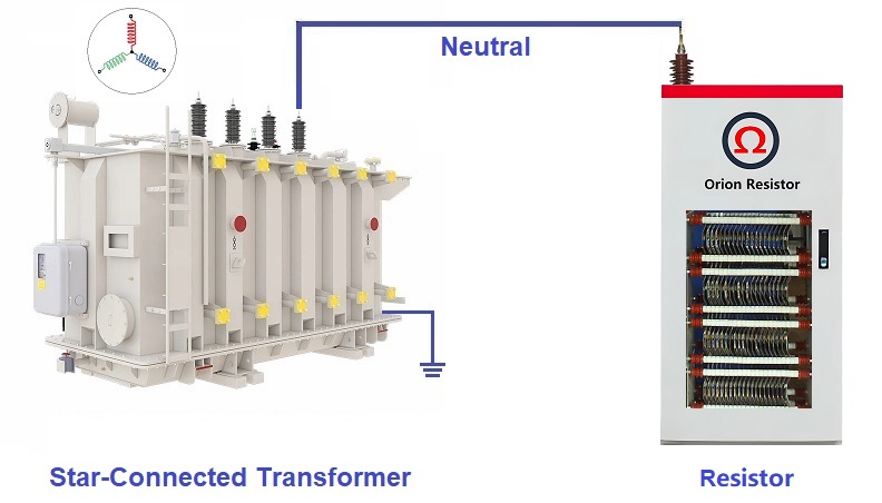
For a transformer with an accessible star-connected neutral point, an NGR is installed between the transformer neutral and earth to limit single-line-to-ground fault current.
However, selecting an NGR is not simply a matter of dividing the transformer phase voltage by a chosen current. Engineers must also consider the grounding philosophy, system capacitive charging current, transformer neutral withstand capability, protection coordination, insulation requirements, and short-time thermal capacity.
This article explains how to determine the appropriate NGR resistance for transformer applications, with practical calculation examples for 3.3 kV and 13.8 kV systems.
1. Understanding the Working Principle of a Transformer NGR
In a resistance-grounded transformer system, the star point of the transformer secondary winding is connected to earth through a neutral grounding resistor.
When a single-line-to-ground fault occurs, the neutral point provides a return path for the fault current. The NGR limits this current to a predetermined value, reducing the thermal and mechanical stress on electrical equipment.
The main functions of an NGR include:
Limiting single-line-to-ground fault current.
Reducing equipment damage at the fault location.
Limiting the risk of damaging transient overvoltages associated with intermittent arcing faults.
Providing a predictable resistive current component for ground fault detection and protection.
Supporting the selected system grounding philosophy.
It is important to distinguish resistance grounding from resonant grounding.
An NGR uses a resistance to limit ground fault current. A Petersen coil, also known as an arc suppression coil, uses an adjustable inductance to compensate for the system's capacitive charging current.
These two grounding methods have different design objectives and should not be treated as interchangeable.
2. High-Resistance Grounding vs. Low-Resistance Grounding
Before calculating the NGR resistance, engineers must determine whether the transformer system will use high-resistance grounding (HRG) or low-resistance grounding (LRG).
The grounding philosophy directly affects the required fault current and resistor value.
2.1 High-Resistance Grounding (HRG)
HRG uses a relatively high resistance to limit single-line-to-ground fault current to a low level.
Typical applications include industrial power distribution systems where continuity of service is important.
In many HRG systems, the first ground fault generates an alarm rather than immediately tripping the circuit breaker. The fault must then be located and cleared according to the operating procedure.
A critical design consideration is the system's total phase-to-earth capacitive charging current.
For effective HRG operation, the resistive current through the NGR is generally selected to be equal to or slightly greater than the total system capacitive charging current.
This relationship helps ensure that the grounding current has a sufficient resistive component and reduces the risk of sustained intermittent arcing overvoltages.
The required margin should be determined according to the grounding design, applicable standards, and project requirements rather than assumed to be a universal fixed value.
2.2 Low-Resistance Grounding (LRG)
LRG uses a lower resistance to permit a higher ground fault current.
It is commonly used in industrial medium-voltage distribution systems where ground faults are expected to be detected and disconnected by protective relays.
The target fault current is primarily determined by:
Ground fault protection sensitivity and coordination.
Transformer neutral and winding short-time withstand capability.
Neutral bushing and grounding conductor thermal ratings.
Acceptable damage at the fault location.
System grounding and overvoltage requirements.
In LRG applications, the resistive current is normally much greater than the system capacitive charging current. Nevertheless, the system capacitance should still be included in the overall grounding study.
The following table summarizes the main differences.
| Parameter | HRG | LRG |
|---|---|---|
| Ground fault current | Low | Higher |
| NGR resistance | High | Lower |
| System capacitance | Critical design consideration | Must be checked |
| First ground fault | Often alarm | Usually trips |
| Main objective | Limit fault current while maintaining continuity | Limit fault current and ensure reliable protection |
| Typical application | Industrial systems requiring continuity | Industrial medium-voltage distribution |
3. Determining the Correct NGR Resistance
For a transformer with a directly grounded star neutral, the initial NGR resistance calculation is based on the phase-to-neutral voltage and the required resistive grounding current.
The basic formula is:
R = Uph / IR
Where:
R = NGR resistance in ohms (Ω).
Uph = Transformer phase-to-neutral voltage in volts (V).
IR = Required resistive current through the NGR in amperes (A).
The phase voltage is calculated as:
Uph = UL / √3
Where UL is the transformer's rated line-to-line voltage.
Therefore:
R = UL / (√3 × IR)
This is the standard preliminary sizing formula for a directly connected neutral grounding resistor.
It assumes that the NGR resistance dominates the grounding path and that other system impedances and fault impedance have a relatively small influence.
For an accurate system fault calculation, transformer and network sequence impedances must also be considered.
3.1 How Should the Target Grounding Current Be Selected?
The target current should not be selected arbitrarily. It depends on the grounding philosophy and the electrical characteristics of the transformer system.
For LRG systems, engineers should consider the following factors:
Protection requirements
The selected grounding current must be sufficient for the installed ground fault protection to detect the fault reliably.
The current transformer ratio, relay pickup setting, sensitivity, and protection coordination must all be considered.
Transformer neutral withstand capability
The selected fault current must remain within the short-time thermal withstand limits of the transformer neutral winding connection, neutral bushing, and associated conductors.
Ground fault damage
Higher fault current may increase damage to the faulted equipment. The selected value should balance protection sensitivity and equipment protection.
System operating voltage
The phase-to-neutral voltage determines the voltage applied across the NGR during a solid single-line-to-ground fault.
For HRG systems, the total system capacitive charging current must also be considered when determining the required resistive current.
4. Calculating System Capacitive Charging Current
System capacitance is particularly important in high-resistance grounding applications.
Although the NGR is physically installed at the transformer neutral, it grounds the entire electrically connected distribution system. Cables, busbars, motors, and other connected equipment contribute to the total phase-to-earth capacitance.
For a balanced three-phase system, the total capacitive charging current during a single-line-to-ground fault can be approximated by:
IC = 3 × ω × C0 × Uph
Where:
IC = Total system capacitive charging current (A).
ω = Angular frequency, equal to 2πf.
C0 = Equivalent phase-to-earth capacitance per phase (F).
Uph = System phase-to-neutral voltage (V).
The NGR resistive current is:
IR = Uph / R
For conventional HRG design, the resistive current is generally selected to be equal to or slightly greater than the total capacitive charging current.
IR ≥ IC
Substituting the two equations gives:
R ≤ 1 / (3 × ω × C0)
This relationship provides a useful preliminary resistance criterion for HRG applications.
However, the equation should not be interpreted as a universal overvoltage limit or a complete transient overvoltage calculation. The definition of capacitance must also be consistent: C0 in this equation represents the equivalent capacitance of each phase to earth.
For LRG applications, the selected resistive current is normally substantially higher than the total capacitive charging current, but system capacitance should still be included in the grounding study.
5. More Accurate Single-Line-to-Ground Fault Calculation
The basic formula R = Uph / IR is suitable for preliminary NGR sizing when the resistor dominates the grounding impedance.
For a more detailed fault study, the symmetrical component method should be used.
The single-line-to-ground fault current can be expressed as:
If = 3 × Uph / (Z1 + Z2 + Z0 + 3Rn + 3Zf)
Where:
If = Single-line-to-ground fault current.
Uph = Prefault phase-to-neutral voltage.
Z1 = Positive-sequence impedance.
Z2 = Negative-sequence impedance.
Z0 = Zero-sequence impedance.
Rn = Neutral grounding resistance.
Zf = Fault impedance.
This expression assumes a simplified single-source equivalent network. For practical systems, the sequence impedances must represent the complete network, including relevant transformer and source contributions.
When the NGR resistance is much greater than the other impedances, the simplified calculation becomes a reasonable approximation.
Engineers should distinguish between the resistive current flowing through the NGR and the total fault current, which may also include capacitive and other network contributions.

6. Practical NGR Resistance Calculation Examples
The following examples demonstrate how to calculate the NGR resistance and short-time power for two common transformer voltage levels.
For simplicity, both examples assume that the NGR resistive current dominates and that the transformer system has an accessible star-connected neutral.
Example 1: 3.3 kV Transformer
Given:
Transformer rated voltage: 3.3 kV.
Selected NGR resistive current: 10 A.
Rated time: 10 seconds.
Step 1: Calculate the phase-to-neutral voltage.
Uph = 3300 / √3
Uph = 1905.26 V
Step 2: Calculate the NGR resistance.
R = 1905.26 / 10
R = 190.53 Ω
Step 3: Calculate the short-time power.
P = Uph × IR
P = 1905.26 × 10
P = 19.05 kW
Step 4: Calculate the theoretical energy during the 10-second duty.
E = P × t
E = 19.05 × 10
E = 190.5 kJ
The preliminary NGR specification is:
System voltage: 3.3 kV.
Rated resistor voltage: 1.905 kV.
Rated current: 10 A.
Resistance: 190.53 Ω.
Short-time power: 19.05 kW.
Rated time: 10 seconds.
Example 2: 13.8 kV Transformer
Given:
Transformer rated voltage: 13.8 kV.
Selected NGR resistive current: 20 A.
Rated time: 10 seconds.
Step 1: Calculate the phase-to-neutral voltage.
Uph = 13800 / √3
Uph = 7967.43 V
Step 2: Calculate the NGR resistance.
R = 7967.43 / 20
R = 398.37 Ω
Step 3: Calculate the short-time power.
P = 7967.43 × 20
P = 159.35 kW
Step 4: Calculate the theoretical energy during the 10-second duty.
E = 159.35 × 10
E = 1593.5 kJ
The preliminary NGR specification is:
System voltage: 13.8 kV.
Rated resistor voltage: 7.967 kV.
Rated current: 20 A.
Resistance: 398.37 Ω.
Short-time power: 159.35 kW.
Rated time: 10 seconds.
These examples demonstrate the calculation method rather than prescribe standard grounding currents for all 3.3 kV or 13.8 kV transformers.
The final current rating must be determined from the actual grounding study, protection requirements, and equipment withstand capability.
7. NGR Rated Voltage and Insulation Requirements
The rated voltage of an NGR should not be confused with the transformer's line-to-line voltage.
When an NGR is connected directly between the transformer neutral and earth, its rated voltage is normally the phase-to-neutral voltage:
Ur = UL / √3
For example:
| Transformer system voltage | NGR rated voltage |
|---|---|
| 3.3 kV | 1.905 kV |
| 6.6 kV | 3.811 kV |
| 10 kV | 5.774 kV |
| 11 kV | 6.351 kV |
| 13.8 kV | 7.967 kV |
| 33 kV | 19.05 kV |
However, selecting the NGR rated voltage is only the first step in insulation design.
The following parameters should also be verified:
Highest voltage for equipment (Um).
Rated power-frequency withstand voltage.
Rated lightning impulse withstand voltage (BIL).
Electrical clearance and creepage distance.
Insulation coordination.
Installation altitude and environmental conditions.
The transformer's neutral bushing insulation level should also be checked with the transformer manufacturer. Neutral insulation is not necessarily identical to the insulation level of the line terminals.
For installations at high altitude or in polluted environments, appropriate insulation corrections and creepage requirements may apply.
8. NGR Short-Time Rating and Thermal Capacity
Most industrial transformer NGRs are designed for short-time operation, although continuous-rated designs are also available for specific applications.
The rated time is the duration for which the resistor must withstand its specified electrical duty.
Common short-time ratings include: 3 seconds / 5 seconds / 10 seconds / 30 seconds / 60 seconds.
The required duration should be determined from the complete protection clearing sequence, including primary protection, circuit breaker operating time, and backup protection.
A 10-second rating is common in industrial applications, but it is not a universal requirement.
The short-time power is calculated as:
P = I²R
Or:
P = Uph × IR
The corresponding theoretical energy is:
E = P × t
The resistor elements must be designed to withstand the required thermal energy without exceeding their permissible temperature limits.
The thermal design should consider:
Resistor element material.
Initial ambient temperature.
Maximum element temperature.
Temperature rise during the rated duty.
Cooling and ventilation conditions.
Resistance variation with temperature.
Repeated fault operations and specified duty cycles.
IEC 60076-25:2023 defines requirements for NGR characteristics, ratings, service conditions, testing, and marking. It also provides guidance on resistance variation with temperature.
The rated resistance should be specified at a defined reference temperature. Under IEC 60076-25:2023, the default rated ambient temperature is 20°C unless otherwise specified, and the default resistance tolerance is ±10% unless the purchaser specifies another value.
For HRG and sensitive protection applications, the maximum resistance variation during heating may need to be more tightly controlled.
9. Transformer and Protection System Checks Before Final Selection
Before approving an NGR design, engineers should verify the following parameters.
1. Transformer neutral connection
Confirm that the transformer has an accessible star-connected neutral point suitable for direct resistance grounding.
2. Transformer neutral withstand capability
Obtain the manufacturer's short-time withstand information for the neutral winding connection, bushing, and associated conductors.
3. Neutral grounding CT and protection relay
Check the CT ratio, accuracy class, relay pickup current, protection sensitivity, and coordination with upstream and downstream devices.
4. System capacitive charging current
Determine the total connected system phase-to-earth capacitance, particularly for HRG applications.
5. Grounding effectiveness and overvoltage
Evaluate the grounding configuration, sequence impedances, fault duration, and healthy-phase voltage rise. Do not rely on a single fixed per-unit overvoltage limit for every system.
6. Rated time and thermal capacity
Confirm that the NGR can withstand the required fault current for the complete specified protection clearing time.
7. Insulation coordination
Verify the NGR rated voltage, power-frequency withstand voltage, lightning impulse withstand voltage, clearances, and creepage distances.
8. Environmental and mechanical requirements
Confirm enclosure protection, corrosion resistance, ambient temperature, altitude, ventilation, installation arrangement, and transportation requirements.
10. Common Mistakes in Transformer NGR Selection
Mistake 1: Selecting NGR resistance without considering system capacitance
This is particularly problematic in HRG systems. The total capacitive charging current must be evaluated to ensure that the selected resistive grounding current is adequate.
Mistake 2: Using the same grounding current for every transformer voltage level
Different systems have different protection requirements, grounding philosophies, and equipment withstand limits. A 10 A NGR is not automatically suitable for every 3.3 kV transformer, nor is a 20 A NGR automatically suitable for every 13.8 kV transformer.
Mistake 3: Treating the simplified resistance formula as an exact fault calculation
The formula R = Uph / IR is a useful preliminary sizing method. For more accurate fault studies, transformer and network sequence impedances and fault impedance must be included.
Mistake 4: Assuming that every NGR must have a 10-second rating
The rated time depends on the protection coordination and project requirements. Other ratings, including 3, 5, 30, and 60 seconds, are also used.
Mistake 5: Ignoring resistance variation with temperature
The resistance at the reference temperature may differ from the resistance during the fault duty. This variation should be specified and considered in the design.
Mistake 6: Selecting insulation based only on the nominal phase voltage
The NGR must also meet the required power-frequency and impulse withstand levels, as well as applicable clearance and creepage requirements.
11. Recommended Engineering Procedure for Transformer NGR Selection
For practical engineering and procurement, the following procedure provides a systematic approach:
Confirm the transformer rated voltage, winding connection, and neutral availability.
Determine whether HRG or LRG is required.
Establish the target resistive grounding current based on the protection philosophy and equipment withstand capability.
Calculate the total system capacitive charging current, particularly for HRG systems.
Calculate the preliminary NGR resistance using the phase-to-neutral voltage and target resistive current.
Perform a detailed ground fault and overvoltage study where required.
Verify transformer neutral thermal withstand capability, CT ratings, and protection coordination.
Determine NGR rated voltage, short-time current, rated time, thermal capacity, resistance tolerance, and insulation level.
Finalize enclosure protection, installation conditions, accessories, and monitoring requirements.
12. Applicable Standards
The following standards provide relevant guidance for transformer NGR design and application:
IEC 60076-25:2023 – Power Transformers, Part 25: Neutral Grounding Resistors.
IEEE C57.32-2015 and IEEE C57.32a-2020 – Requirements, Terminology, and Test Procedures for Neutral Grounding Devices and related amendment.
IEEE C62.92.1 – Guide for the Application of Neutral Grounding in Electrical Utility Systems.
IEEE 3003.1-2019 – Recommended Practice for System Grounding of Industrial and Commercial Power Systems.
The applicable edition and status of each standard should be confirmed when preparing project specifications. IEC 60364 is primarily concerned with low-voltage electrical installations and should not be used as the principal product standard for medium-voltage NGRs.
Conclusion
Selecting the correct transformer neutral grounding resistor requires more than a simple resistance calculation. The grounding philosophy, target resistive current, system capacitive charging current, transformer neutral withstand capability, protection coordination, insulation requirements, and short-time thermal capacity must all be considered.
For preliminary sizing, the relationship between phase voltage, NGR resistance, and resistive grounding current provides a practical starting point. However, the final design should be verified through an appropriate grounding and protection study.
By following these engineering principles and applying the relevant IEC and IEEE standards, engineers can select an NGR that provides reliable ground fault limitation, effective protection coordination, and long-term equipment reliability.

CATEGORIES
- Neutral Grounding Resistor for Transformer
- Generator Neutral Grounding Resistor
- Low Voltage Neutral Grounding Resistor
- Neutral Grounding Arc Suppression Coils (Peterson Coil)
- Neutral Point Gap Grounding Protection Device
- Nitrogen Injection Fire Protection System for Transformer (NIFPS)
- Transformer Air-Cooled Control Equipment
- Nonlinear Neutral Grounding Equipment
LATEST NEWS
- Why Does the Neutral Point of a Large Generator Need to be Reliably Grounded?
- Transformer Neutral Grounding Methods and Applications for High-, Medium-, and Low-Voltage Systems
- How to Accurately Calculate the Neutral Grounding Resistance Value of a Transformer
- Global Top 8 Neutral Grounding Resistor (NGR)Manufacturers
- How to Select the Correct Neutral Grounding Resistor (NGR) for a Transformer
CONTACT US
WhatsApp:
Tel: +86-312-5959618
Email: info@orionresistors.com
Add: No. 79, Fuchang Road, Zhongguancun Entrepreneurship Base, Baoding City,China