How to Size a Neutral Grounding Resistor (NGR)?
Writer: admin Time:2026-01-13 18:27:53 Browse:267℃
Neutral grounding resistors (NGRs) for transformers and generators are critical power system devices installed by connecting resistive elements between the equipment neutral point and earth. Their primary functions are to limit ground-fault current and suppress overvoltages, thereby enhancing system safety and operational reliability.
The core purpose of an NGR is to prevent arc re-ignition and resonant overvoltages that may occur during single-line-to-ground faults in ungrounded or resonant-grounded (Petersen coil) systems. By accurately controlling ground-fault current, the NGR reduces insulation stress and equipment damage while ensuring reliable operation of protective relays. Proper selection is essential; incorrect rating or configuration may result in equipment failure, misoperation of protection, or system outages.
Taking an 11 kV power system as an example, the following sections describe the correct and systematic procedure for selecting a neutral grounding resistor.
Selection Priority
Basic system parameters → Current-related calculations → Performance and environment → Standards and certification
Step 1: Define Basic System Parameters
(Fundamental prerequisites — must be determined first)
Basic system parameters establish the selection framework for the NGR. Any mismatch at this stage renders subsequent current and resistance calculations meaningless. The following items must be clearly identified:
1. System Voltage Level
The rated voltage of the NGR must precisely match the system voltage, including line-to-line and line-to-neutral values. Typical applications include 6 kV, 11 kV, and 35 kV systems. Voltage mismatch may cause insulation breakdown or improper operation.
Example:
For an 11 kV three-phase AC distribution system, the phase voltage is approximately:
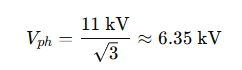
Therefore, an NGR specifically rated for 11 kV systems must be selected. Products designed for 10 kV or other non-matching voltage classes are unacceptable.
2. Neutral Grounding Arrangement and Main Equipment Type
It is necessary to identify whether the neutral point belongs to a transformer, generator, or distribution system, and to confirm the winding connection of the main transformer (star or delta). Different configurations impose fundamentally different design requirements on the NGR.
Example:
In an 11 kV cable distribution system with a star-connected transformer (YNyn0), the neutral point can be directly grounded through the NGR.
If the transformer is delta-connected and no neutral point is available, a grounding transformer must first be installed to create an artificial neutral, which is then connected to the NGR.
3. Brief Notes on Grounding Transformer Selection (for 11 kV Systems)
1) Type selection
Dry-type cast-resin grounding transformers are preferred for both indoor and outdoor installations. Insulation class F or higher is recommended to meet 11 kV withstand requirements.
2) Voltage ratio
For an 11 kV delta-connected system requiring a neutral point, a typical voltage ratio is:

The primary side matches the system voltage, while the secondary provides standard low voltage for protection and measurement.
3) Turns and impedance considerations
The turns ratio follows the voltage ratio principle. The primary winding is designed for the 11 kV/√3 phase voltage to ensure a low magnetizing current (≤3% of rated current) and to avoid core saturation. The transformer impedance voltage is typically 4%–6%, coordinated with system ground-fault current requirements.

Step 2: Calculate Charging Current and Target Ground-Fault Current
(Core analytical basis for resistance selection)
The system charging current (capacitive earth-fault current) is a key parameter, but it must be evaluated together with the target ground-fault current to derive the correct resistance value.
1. Charging Current Estimation
Charging current depends on the total length of cables or overhead lines and their distributed capacitance. It can be calculated analytically or measured on site.
Reference formula:
For an 11 kV single-core cable system:

Example:
If the total cable length is 40 km:
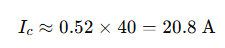
Measured values should be within ±10% of the calculated result.
2. Determination of Target Ground-Fault Current
The target ground-fault current must be greater than or comparable to the charging current to suppress arc re-ignition, while remaining within safe limits. For 11 kV systems, typical values range from 5 A to 20 A.
Example:
With a charging current of 20.8 A, a target ground-fault current of 15 A is selected, balancing overvoltage suppression and equipment protection.
3. Resistance Calculation
The neutral grounding resistance is calculated as:
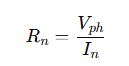
Where:
( Rn ) = neutral grounding resistance
( Vph ) = system phase voltage
( In ) = target ground-fault current
Example: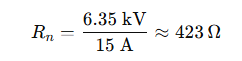
In practice, standard resistor values such as 420 Ω or 450 Ω may be selected.
Step 3: Match Resistor Type, Performance, and Environmental Conditions
Based on the parameters determined above, the final selection must consider construction, performance, and installation environment.
1. Resistor Type
Metallic resistors (e.g., stainless steel) offer high thermal endurance and long-term stability and are widely used in 11 kV distribution systems.
In corrosive environments (chemical plants, coastal areas), anti-corrosion or non-metallic resistors may be preferred.
For temporary or commissioning applications, liquid resistors with adjustable resistance can be used.
Example:
For a standard industrial park 11 kV system, a stainless-steel NGR cabinet is selected.
2. Key Performance Verification
Resistance tolerance: ≤ ±10%
(e.g., a 420 Ω resistor must fall within 378–462 Ω)Rated short-time current duration: typically 10 s, coordinated with relay operation time
Insulation level: higher than the maximum system voltage, preferably Class F or above
Temperature rise limit: ≤ 385 °C for metallic resistors
3. Environmental Adaptation
Outdoor installations: minimum IP54, preferably IP55, with rain- and sun-proof enclosure
Indoor installations: adequate ventilation and heat dissipation required
Hazardous areas: explosion-proof design compliant with IECEx or equivalent standards
Example:
For an outdoor industrial park application, an IP55-rated stainless-steel NGR cabinet is selected.
CATEGORIES
- Neutral Grounding Resistor for Transformer
- Generator Neutral Grounding Resistor
- Low Voltage Neutral Grounding Resistor
- Neutral Grounding Arc Suppression Coils (Peterson Coil)
- Neutral Point Gap Grounding Protection Device
- Nitrogen Injection Fire Protection System for Transformer (NIFPS)
- Transformer Air-Cooled Control Equipment
- Nonlinear Neutral Grounding Equipment
LATEST NEWS
- Why Does the Neutral Point of a Large Generator Need to be Reliably Grounded?
- Transformer Neutral Grounding Methods and Applications for High-, Medium-, and Low-Voltage Systems
- How to Accurately Calculate the Neutral Grounding Resistance Value of a Transformer
- Global Top 8 Neutral Grounding Resistor (NGR)Manufacturers
- Neutral Grounding Resistor (NGR) Sizing – Step-by-Step Practical Guide
CONTACT US
WhatsApp: +86-18631228466
Tel: +86-312-5959618
Email: info@orionresistors.com
Add: No. 79, Fuchang Road, Zhongguancun Entrepreneurship Base, Baoding City,China