How to Select the Right Neutral Grounding System for 6–35 kV Distribution Grids
Writer: admin Time:2025-10-31 15:53:59 Browse:324℃
Introduction
In a three-phase AC power system, the electrical connection between the system neutral point and ground is known as the neutral grounding method. The grounding mode affects system reliability, insulation coordination, overvoltage level, relay protection, and communication interference. In practice, the grounding of transformer neutrals at various voltage levels defines the system grounding type, and its selection should be analyzed carefully during substation planning.
At voltages of 110 kV and above, most international systems adopt effective (solid) grounding, ensuring low overvoltage and reliable fault clearing. In some networks, transformers may remain ungrounded to reduce earth fault current. When effectively grounded, the neutral potential is near ground potential; during a single-phase fault, the healthy-phase voltage does not exceed 1.4 times the rated phase voltage. This limits transient overvoltage and shortens fault duration, allowing equipment insulation levels and overall investment to be reduced.
For 6–35 kV distribution networks, low-current grounding systems are more common. With growing network capacitance, improper grounding may endanger safe operation. The typical low-current grounding types are:
Ungrounded systems
Arc-suppression coil (Petersen coil) grounding
Resistance grounding
1. Ungrounded Neutral System
This method suits networks dominated by overhead lines where the single-phase capacitive fault currentIC≤10A. It is widely used in rural or remote 10 kV systems. In such grids, around 60–70 % of single-phase faults are transient, and non-tripping operation is preferred.
Advantages:
ForIC≤10A, the fault arc extinguishes naturally, and insulation self-recovers.
The system can operate with a fault temporarily, maintaining power supply continuity.
Low communication interference.
Disadvantages:
During a single-phase fault, the healthy-phase voltage rises to; equipment insulation must be designed for line voltage.
IfIC>10A, the fault arc cannot self-extinguish, causing intermittent arcing overvoltages that may damage weak insulation and lead to double-earth faults or outages.
Resonant overvoltages may blow PT fuses or damage main equipment.
2. Arc-Suppression Coil Grounding
This method suits networks whereIC>10A and transient faults dominate. The arc-suppression coil (Petersen coil) generates inductive current to offset capacitive earth-fault current, limiting the residual current to ≤ 10 A, allowing arc extinction and insulation recovery.
Main advantages:
Reduces arcing ground overvoltages.
Enables short-term operation with fault.
Decreases ground potential rise and step voltage.
Minimizes interference to low-voltage and communication systems.
Two types are used internationally: manually adjustable and automatic tracking coils.
The manual type requires manual tuning and system outage—now rarely used.
The automatic type measures system capacitance and adjusts compensation in real time—now the mainstream option.
Automatic systems include:
Tap-adjusting type: simple but limited steps.
Air-gap type: better linearity but noisy.
DC-biased (magnetically assisted) type and capacitor-controlled type: fast, quiet, and reliable—the preferred modern solution.
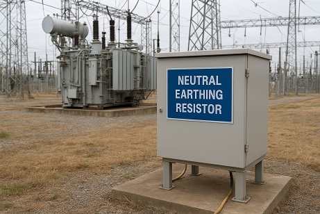
3. Resistance Grounding
This method is used mainly in urban distribution networks with cable lines, where transient faults are fewer.
Features:
Reduces switching and power-frequency overvoltage.
Zero-sequence protection can accurately detect and isolate the fault line.
Limits arcing ground overvoltage, as residual charge in system capacitance discharges through the neutral resistor.
Prevents resonance overvoltage, since the resistor provides damping in the resonant loop.
Applicable over a wide range of capacitive currents, simple and reliable.
Selection of Neutral Grounding Resistor:
The resistor valueRn should balance:
Smaller fault current for personnel safety (reduces step and touch voltage).
Sufficient damping to limit arcing ground overvoltage (keep within 2 p.u.).
Typically,IR=(1–4)IC is recommended.
The zero-sequence protection sensitivity must also remain adequate.
A resistor value ≤ 1500 Ω generally suppresses resonance effectively.
4. Grounding Selection for 6–35 kV Networks
For networks dominated by overhead lines, where about 70 % of earth faults are transient, either ungrounded or automatic arc-suppression coil grounding is recommended, depending on whetherIC exceeds 10 A.
For cable-dominant networks, system capacitance is higher and transient faults fewer. In such cases, low-resistance grounding is preferred, accepting a small loss of reliability to prevent fault escalation.
For mixed networks (overhead + cable), choosing between coil and resistor grounding is challenging. Problems include:
Prolonged voltage rise on healthy phases.
Arc-suppression coil cannot compensate harmonic currents (often 5–15 % of total), which may sustain the arc.
Difficulty locating faulted feeders, especially in cable trenches.
Potential safety hazards during “fault-on” operation.
Low-resistance grounding may trip transient faults unnecessarily, reducing supply reliability.
5. Recommended Solution for Mixed Networks
To improve insulation, cables rated at 8.7/10 kV or 12/15 kV should be used. An automatic tracking arc-suppression coil combined with a small-current fault locator is recommended.
A new hybrid grounding device—combining an automatic arc-suppression coil with a parallel small resistor controlled by a microprocessor—is under development. Its principle:
Upon a transient ground fault, only the coil operates.
If the fault persists, the microprocessor judges it as permanent and switches in the resistor to trigger protection and isolate the faulty feeder.
This hybrid design may effectively solve grounding issues in mixed networks.
Conclusion
Different grounding methods have distinct advantages and limitations. Selection should be based on actual system characteristics, balancing insulation, protection, interference, and safety—not solely on voltage level.


CATEGORIES
- Neutral Grounding Resistor for Transformer
- Generator Neutral Grounding Resistor
- Low Voltage Neutral Grounding Resistor
- Neutral Grounding Arc Suppression Coils (Peterson Coil)
- Neutral Point Gap Grounding Protection Device
- Nitrogen Injection Fire Protection System for Transformer (NIFPS)
- Transformer Air-Cooled Control Equipment
- Nonlinear Neutral Grounding Equipment
LATEST NEWS
- Why Does the Neutral Point of a Large Generator Need to be Reliably Grounded?
- Transformer Neutral Grounding Methods and Applications for High-, Medium-, and Low-Voltage Systems
- How to Accurately Calculate the Neutral Grounding Resistance Value of a Transformer
- Global Top 8 Neutral Grounding Resistor (NGR)Manufacturers
- Neutral Grounding Resistor (NGR) Sizing – Step-by-Step Practical Guide
CONTACT US
WhatsApp: +86-18631228466
Tel: +86-312-5959618
Email: info@orionresistors.com
Add: No. 79, Fuchang Road, Zhongguancun Entrepreneurship Base, Baoding City,China