How are the grounding resistor value and grounding transformer for a 35 kV distribution system determined?
Writer: admin Time:2025-09-19 10:31:31 Browse:547℃
1. Current System Design and Capacitive Current Calculation
The substation has a total of three main transformers, connected in Y/Δ, with rated voltages of 110 kV/35 kV. The 35 kV distribution system is entirely cable-based. Based on the 35 kV cable types and lengths in the substation, the system capacitive current is calculated as follows:
According to substation engineers, the capacitive currents for buses I, II, and III are each Ic = 50 A.
There are three 35 kV buses, all of which are grounded via neutral grounding resistors. Therefore, the total capacitive current considering parallel operation is:
Ic_total = Ic_I + Ic_II + Ic_III = 50 A + 50 A + 50 A = 150 A
Considering future load growth and other substation equipment, the total system capacitive current is taken as:
Ic_total = 150 A × 1.2 = 180 A
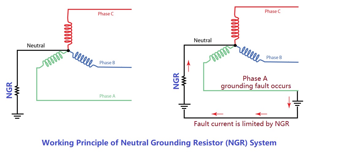
2. Advantages of Neutral Resistor Grounding
The main purpose of using neutral resistor grounding for the 35 kV substation system is to limit system overvoltage and achieve fast and accurate fault line selection under single-phase ground faults.
The two primary advantages of neutral resistor grounding are:
Effectively limiting all types of overvoltages, especially intermittent arc-ground overvoltages.
Using a sufficiently large ground fault current to solve line selection difficulties and enable fast and accurate fault line isolation.
Neutral resistor grounding is particularly suitable for cable-dominated distribution networks, large industrial and mining enterprises, airports, ports, subways, steel plants, as well as power plants and auxiliary systems. Its main advantages include:
Reduces power-frequency overvoltage; voltage rise of non-faulted phases is less than 1.33 p.u.
Effectively limits intermittent arc-ground overvoltages.
Eliminates resonant overvoltages and reduces operational overvoltages.
Enables accurate identification and timely disconnection of faulted lines.
Reduces the magnitude and duration of overvoltage, allowing lower equipment insulation levels, improving system component lifespan, and providing economic benefits.
Facilitates the use of MOA ZnO surge arresters with excellent volt-second characteristics, lowering lightning overvoltage; suitable for future system expansion and wide variations in capacitive current, with no need to adjust the resistor; equipment is simple, reliable, low-investment, and long-lasting.
3. Selection of Neutral Grounding Resistor
The selection of neutral grounding resistors is primarily based on the total system capacitive current.
When using neutral resistor grounding, the resistor value must consider system-specific factors such as overvoltage limitation, relay sensitivity, impact on communications, and personnel safety.
For the 35 kV distribution system, the selected neutral grounding resistor is 33.7 Ω, giving a rated current of IR = 600 A during a single-phase ground fault. The rated short-time withstand current is considered for 10 seconds. Selection rationale includes:
1) Limiting distribution system overvoltage:
Neutral resistor grounding can reduce arc-ground overvoltages, ensuring safe operation of electrical equipment. EMTP simulations, overvoltage test devices, and operating experience indicate that the arc-ground overvoltage level decreases as the resistor rated current IR increases relative to the system capacitive current IC:
IR ≈ IC: overvoltage ≤ 2.5 p.u.
IR ≈ 2IC: overvoltage ≤ 2.2 p.u.
IR ≈ 4IC: overvoltage ≤ 2.0 p.u.
When IR > 4IC, the reduction effect is minimal.
The steady-phase voltage rise due to internal overvoltage is limited by the presence of RN. During arc extinction and re-ignition, excess charge is discharged through RN within half a cycle. When RN < (1–2)/(3ωC), overvoltage is generally ≤ 2.1 times phase voltage.
Using β = IR / IC = 600 A / 180 A = 3.33, the calculated steady-phase voltage rise ratio is Kb = Kc = 1.58 p.u. Thus, IR = 4IC limits intermittent arc-ground overvoltage to ≤ 2.0 p.u. and power-frequency overvoltage to ≤ 1.58 p.u.
2) Protection relay settings:
For single-phase faults on a 35 kV feeder, the grounding fault current is:
Ijd = √(IR² + IC²) = √(600² + 180²) ≈ 626.4 A
This current is sufficient to satisfy zero-sequence relay sensitivity requirements. The chosen resistor ensures proper operation without false trips.
3) Communication impact:
Grounding resistor current should not be excessively large to avoid communication interference. Experience from Shenzhen, Guangzhou, and Shenyang metro lines shows 600 A has no adverse effect. Tests by Shanghai power authority confirm that even 1000 A does not exceed permissible interference voltages.
4) Personnel safety:
Smaller resistor current is safer. Low-resistance grounding may elevate ground potential at the fault point, causing step and touch voltages. Considering local grounding and protection times, 600 A is a safe choice.
4. Grounding Transformer Principles, Characteristics, and Capacity Selection
4.1 Connection Principle
If the main transformer secondary is delta or star without a neutral, a zig-zag (Z) grounding transformer can create an artificial neutral. The grounding resistor connects to this neutral, as shown in the diagram.

Characteristics of Z-type grounding transformer:
Each phase winding is split into two sections with opposite polarity; connected in a Z-shape to form a star.
High impedance for positive and negative sequence currents (like excitation impedance), small excitation current flows.
Low impedance for zero-sequence currents; zero-sequence voltage drop is minimal.
4.2 Capacity Selection
According to IEEE C62.92.3, the 10-second overload factor is 10.5.
Given:
System voltage: UN = 35 kV
Phase voltage: Uφ = 20.2 kV
Resistor short-time current (10 s): I10s = 600 A
Resistor value: RN = 33.7 Ω
Short-time duration: 10 s
10-second short-time capacity:
S10s = 3 × Uφ × I10s / 3 = 3 × 20.2 × 600 / 3 = 12,120 kVA
Continuous-rated capacity:
SN = S10s / 10.5 ≈ 1,154 kVA → rounded to 1,200 kVA
Selected transformer: DKSC-1200 kVA / 35 kV
5. Zero-Sequence CT Configuration and Protection Settings
5.1 Overview
Time-delayed zero-sequence overcurrent protection or single-phase ground directional protection enables accurate fault line detection and selective line tripping.
5.2 Zero-Sequence CTs
Use dedicated zero-sequence CTs.
5.3 Single-Phase Ground Protection
Install time-delayed zero-sequence protection at the head of each feeder.
Main transformer low-voltage side receives zero-sequence protection reflecting single-phase faults, serving as main protection for bus faults and backup for feeder faults.
5.4 Setting Primary Pickup Current
Idz1 = KK × Ic1
Where:
Idz1 = relay pickup current
KK = reliability factor
Ic1 = feeder’s capacitive current
For 35 kV feeders with ~7.14 A capacitive current, recommended pickup: Idz1 = 60 A. Suggested operation time: 0.5 s. CT parameters: 300/5 A, 10P10, 20 VA.
6. Orion Intelligent Neutral Grounding Resistor Monitoring Device
The Orion device monitors the operation of the neutral resistor cabinet in real time, including rated current, resistance, and cabinet temperature. During a single-phase fault, it records fault current, resistor value, fault duration, and temperature changes. It supports remote monitoring via RS485 and MODBUS. The device integrates data acquisition, control, and alarm functions.
7. Neutral Grounding Resistor Selection
This substation employs neutral resistor grounding, fully meeting the requirements for reducing system overvoltage and fast, accurate fault line selection. The recommended configuration for each set is as follows:
Serial Number | Product Name | Model Specification | Quantity | Remarks |
1 | Resistance Element | NGR35kV - 600A - 10s33.67Ω, 760K | 1 | Special stainless steel alloy material |
2 | Grounding Transformer | ORSC - 1200kVA/35kV | 1 | |
3 | Current Transformer | ORBJ9 - 10A1300/5, 0.5/10P10, 20VA | 1 | |
4 | Intelligent Monitoring Device | FM160 - 1A | 1 | |
5 | Shell of Grounding Complete Device | Indoor, cold - rolled steel plate4000×2800×3000 | 1 |
Related Articles:
How to Accurately Calculate the Neutral Grounding Resistance Value of a Transformer
Global Top 8 Neutral Grounding Resistor (NGR)Manufacturers
Transformer Neutral Grounding Methods and Applications for High-, Medium-, and Low-Voltage Systems
Solid, Resistance, and Ungrounded Systems — Which Is Safer for your Network?
Why Does the Neutral Point of a Large Generator Need to be Reliably Grounded?


CATEGORIES
- Neutral Grounding Resistor for Transformer
- Generator Neutral Grounding Resistor
- Low Voltage Neutral Grounding Resistor
- Neutral Grounding Arc Suppression Coils (Peterson Coil)
- Neutral Point Gap Grounding Protection Device
- Nitrogen Injection Fire Protection System for Transformer (NIFPS)
- Transformer Air-Cooled Control Equipment
- Nonlinear Neutral Grounding Equipment
LATEST NEWS
- Why Does the Neutral Point of a Large Generator Need to be Reliably Grounded?
- Transformer Neutral Grounding Methods and Applications for High-, Medium-, and Low-Voltage Systems
- How to Accurately Calculate the Neutral Grounding Resistance Value of a Transformer
- Global Top 8 Neutral Grounding Resistor (NGR)Manufacturers
- Neutral Grounding Resistor (NGR) Sizing – Step-by-Step Practical Guide
CONTACT US
WhatsApp: +86-18631228466
Tel: +86-312-5959618
Email: info@orionresistors.com
Add: No. 79, Fuchang Road, Zhongguancun Entrepreneurship Base, Baoding City,China