
Nitrogen Injection Fire Protection System for Transformers (NIFPS)
- Product Feature:
- INQUIRY
Fire Risk of Oil-Immersed Power Transformers
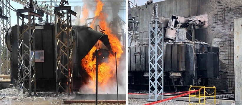
Oil-immersed power transformers are inherently at risk of fire. Continuous overheating of the iron core or transient high temperatures caused by internal arc faults (due to short circuits or overvoltage) can raise the oil temperature above 400 °C. At this point, transformer oil decomposes into various flammable gases, increasing internal tank pressure. When the pressure exceeds the mechanical limits of weak points such as bushings, welds, or explosion vents, hot oil and gas are expelled, ignite upon contact with air, and may lead to fire or even explosion.
Product Overview
The OR-NIFPS Series Oil Drainage and Nitrogen Injection Fire Extinguishing System (hereafter referred to as the System) is designed to automatically extinguish transformer fires by removing overheated oil and injecting nitrogen gas to suppress combustion and cool the oil surface below its flash point.
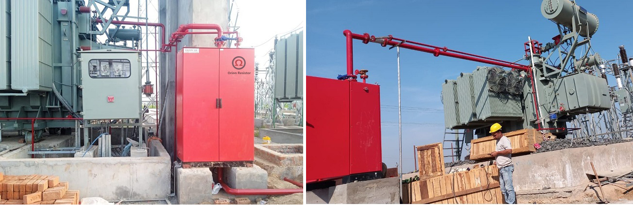
System Composition
The system consists of the following major components:
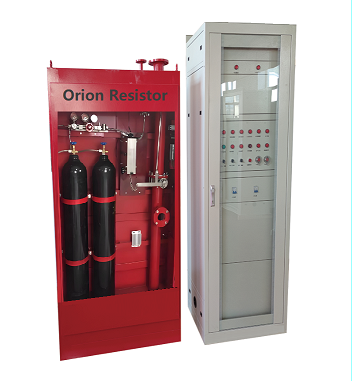
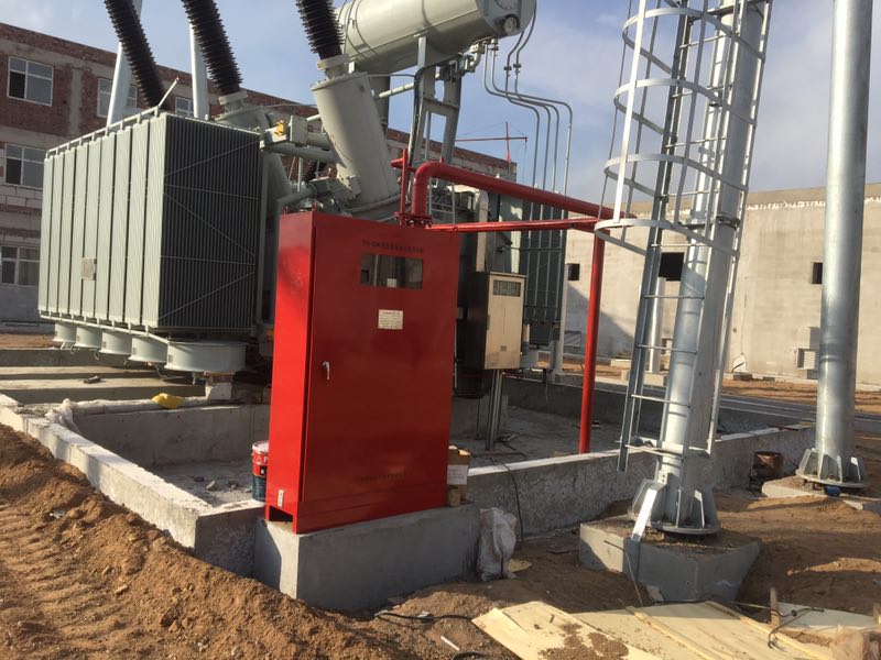
- Fire control cabinet
- Electrical control panel
- Oil drainage and nitrogen injection pipelines
- Temperature detectors
- Shut-off and control valves
- Nitrogen cylinders with pressure regulation
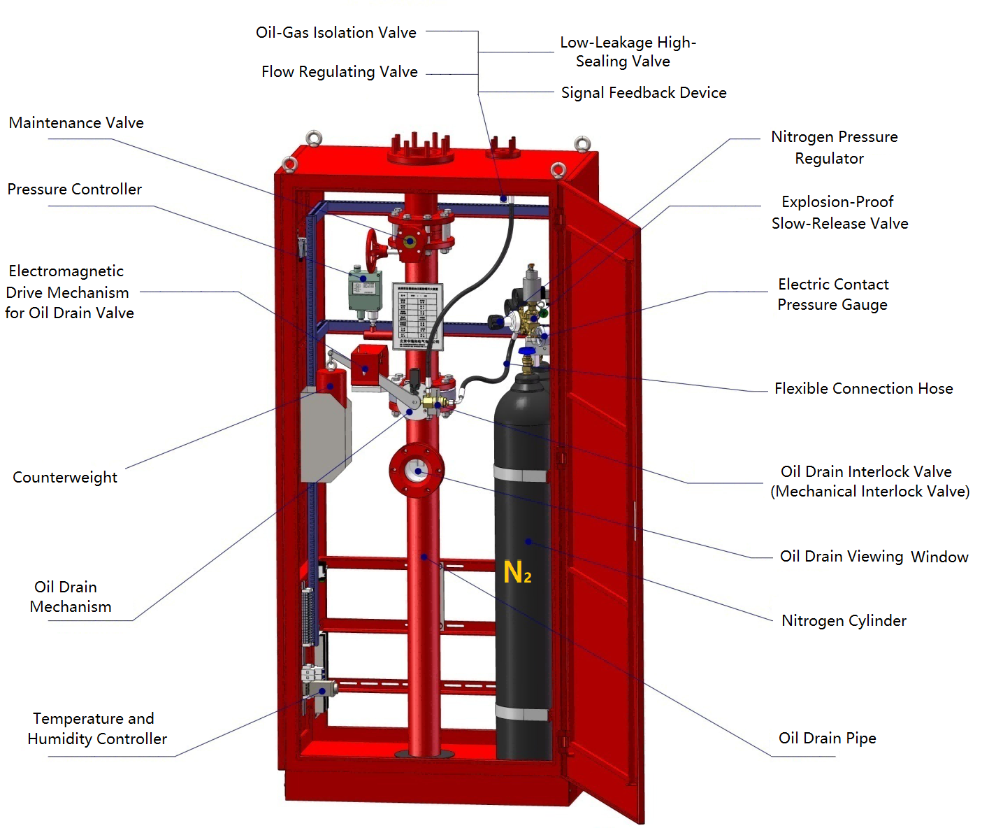
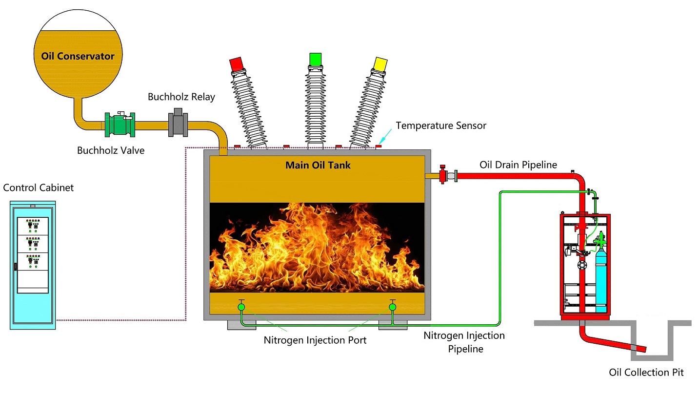
Interal Structure and Key Components of Nitrogen Injection Fire Protection System (OR-NIFPS):
Operation Principle
When a fault occurs inside the transformer, the gas relay trips due to a sudden pressure increase. If the internal temperature continues to rise, the thermal detector activates at its preset temperature (93 ± 2 °C), closing its circuit and triggering the electromagnetic actuator to open the fast oil drain valve, releasing the upper hot oil layer. After a short delay (0–20 s), the control valve opens the nitrogen cylinder. Nitrogen passes through the pressure regulator and injection line into the tank bottom, promoting oil circulation and cooling. This mixing eliminates the hot oil layer and lowers the surface temperature below the flash point, extinguishing internal flames automatically. The shut-off valve prevents oil from the conservator from feeding into the tank during discharge, avoiding fire escalation.
5. Technical Parameters
Item | Specification |
Nitrogen cylinder volume | 0.04 m³ / 0.05 m³ / 0.063 m³ |
Nominal gas pressure | 13–15 MPa |
Oil drainage pipe diameter | DN100 / DN125 / DN150 |
Nitrogen injection pipe diameter | DN25 |
Fire cubicle weight | 230–240 kg |
Control voltage | DC 220 V ± 5% |
Detector activation temperature | 93 ± 2 °C |
Effective nitrogen injection duration | 10–30 min |
Operating temperature range | −40 °C – +60 °C |
Altitude | < 2000 m |
6. Product Advantages
The OR-NIFPS series replaces traditional electromagnetic and counterweight mechanisms with a mechatronic control structure, ensuring precise and reliable action. This innovation eliminates issues such as corrosion-induced jamming or malfunction, and allows reactivation without component replacement—significantly reducing maintenance costs and extending service life.
7. Notes and Limitations
This system is not applicable for extinguishing external fires on transformer surfaces or inside tap-changer compartments.
RELATED PRODUCTS

CATEGORIES
- Neutral Grounding Resistor for Transformer
- Generator Neutral Grounding Resistor
- Low Voltage Neutral Grounding Resistor
- Neutral Grounding Arc Suppression Coils (Peterson Coil)
- Neutral Point Gap Grounding Protection Device
- Nitrogen Injection Fire Protection System for Transformer (NIFPS)
- Transformer Air-Cooled Control Equipment
- Nonlinear Neutral Grounding Equipment
LATEST NEWS
- Why Does the Neutral Point of a Large Generator Need to be Reliably Grounded?
- Transformer Neutral Grounding Methods and Applications for High-, Medium-, and Low-Voltage Systems
- How to Accurately Calculate the Neutral Grounding Resistance Value of a Transformer
- Global Top 8 Neutral Grounding Resistor (NGR)Manufacturers
- Neutral Grounding Resistor (NGR) Sizing – Step-by-Step Practical Guide
CONTACT US
WhatsApp: +86-18631228466
Tel: +86-312-5959618
Email: info@orionresistors.com
Add: No. 79, Fuchang Road, Zhongguancun Entrepreneurship Base, Baoding City,China