How to Calculate the Neutral Grounding Resistor (NGR) Value for an 11kV Transformer?
Writer: admin Time:2025-11-27 13:52:19 Browse:296℃
Why is Resistance Grounding Needed for 11kV Systems?
In 11kV distribution systems, the common operating methods include ungrounded neutral or grounding through an arc suppression coil. However, as the proportion of cable lines increases, the system's capacitive current to ground also increases. When a single-phase ground fault occurs in an ungrounded neutral system, the voltage of the non-faulted phase will rise to line voltage. This sustained high voltage can cause long-term damage to the insulation of grid equipment, and the arc at the fault point can generate intermittent arc-flash overvoltage, severely threatening system safety.
The use of low resistance grounding (LRG) for the neutral point is designed to effectively limit the single-phase ground fault current and suppress system overvoltage. The resistance limits the fault current to a predetermined safe level (typically several hundred to a thousand amperes), which is sufficient to ensure that relay protection devices operate reliably and quickly isolate the fault, preventing insulation damage and equipment burnout.
Grounding Resistance Value Calculation
The selection of the grounding resistance value is critical to the resistance grounding system. The basic principle is that the resistance should be low enough to limit overvoltage but high enough to limit the fault current. The value of is primarily determined by the maximum allowable single-phase ground fault current . The ideal calculation formula is:
The ideal calculation formula is:
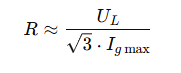
Where:
( UL ) is the system's rated line voltage (11kV).
( Igmax ) is the maximum allowable ground fault current.
In practical applications, the influence of the system's total capacitive current ( Ic ) must also be considered. To ensure the sensitivity of relay protection, it is typically required that ( Igmax ≥3 Ic ).
The selection of the grounding resistance is a comprehensive engineering issue, requiring a balance between limiting fault current, ensuring proper coordination of protection sensitivity, and suppressing transient overvoltage.
3. Selection and Integration of Key Accessories
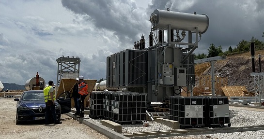
Transformer (Grounding Transformer)
Since most 11kV transformers are connected in a Δ/Y configuration (with the neutral point on the Y side) or do not have a neutral point lead, a grounding transformer (also known as an artificial neutral point grounding device) is often required. The grounding transformer typically adopts a Z-shaped wiring (zigzag connection) to provide a stable artificial neutral point. The Neutral Earthing Resistor (NER) is connected between this neutral point and the ground.Metering and Protection (CT, PT)
a.Current Transformer (CT): Used to monitor the current flowing through the neutral point grounding resistor. The transformation ratio should be selected based on the maximum fault current ( Igmax ), ensuring accurate signal generation for protection during faults.
b.Voltage Transformer (PT): Used to monitor the voltage across the resistor or the system's zero-sequence voltage, which is an important input for zero-sequence voltage protection.
Intelligent Control System
Modern resistance grounding cabinets should integrate an intelligent monitoring system. The system should be capable of:a. Real-time monitoring of the NER’s current and temperature.
b. Fault recording and event logging functions.
c. Remote communication interface, which can be connected to the substation’s comprehensive automation system (SCADA).

4. Cabinet and Insulation Requirements
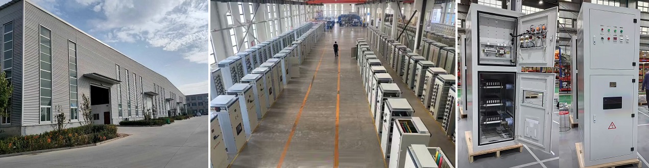
Cabinet Material and Structure
The grounding resistor is typically installed in a dedicated neutral point grounding resistor cabinet.a. Material: The cabinet should be made of stainless steel or high-quality steel with a corrosion-resistant surface treatment, suitable for outdoor or harsh environments, ensuring long-term durability.
b. Structure: The cabinet must have good heat dissipation performance, as significant Joule heat is generated when fault current passes through the resistor. The top and bottom of the cabinet should have ventilation openings and be equipped with dust-proof mesh.
Insulation and Temperature Rise
a. Resistor Material: Special alloys, such as nichrome (nickel-chromium alloy), are typically used due to their high-temperature resistance and low temperature coefficient of resistance.
b.Insulation Rating: The insulation of the resistor and lead wires must meet the voltage withstand requirements of the 11kV system.
c.Temperature Rise: The temperature rise of the resistor must be strictly controlled after flowing through the maximum fault current for a specified duration (e.g., 10 seconds), ensuring it does not exceed the design’s permissible limit. This is one of the key parameters in designing the grounding resistor cabinet.


CATEGORIES
- Neutral Grounding Resistor for Transformer
- Generator Neutral Grounding Resistor
- Low Voltage Neutral Grounding Resistor
- Neutral Grounding Arc Suppression Coils (Peterson Coil)
- Neutral Point Gap Grounding Protection Device
- Nitrogen Injection Fire Protection System for Transformer (NIFPS)
- Transformer Air-Cooled Control Equipment
- Nonlinear Neutral Grounding Equipment
LATEST NEWS
- Why Does the Neutral Point of a Large Generator Need to be Reliably Grounded?
- Transformer Neutral Grounding Methods and Applications for High-, Medium-, and Low-Voltage Systems
- How to Accurately Calculate the Neutral Grounding Resistance Value of a Transformer
- Global Top 8 Neutral Grounding Resistor (NGR)Manufacturers
- Neutral Grounding Resistor (NGR) Sizing – Step-by-Step Practical Guide
CONTACT US
WhatsApp: +86-18631228466
Tel: +86-312-5959618
Email: info@orionresistors.com
Add: No. 79, Fuchang Road, Zhongguancun Entrepreneurship Base, Baoding City,China